AGX Orin Fan Tachometer Always Reads 0

On Jetson AGX Orin module, with custom carrier board, Jetpack 6.2.1.

My fan tachometer reading is always 0, despite the fan moving. This results in nvfancontrol slowly ramping the fan speed up to 100% and staying there.

(The current workaround I’m using is to kill nvfancontrol and manually set PWM to around half speed).

Probing with an oscilloscope, I see the tachometer reading is very weak / noisy. You can see there is a reading, but it appears as if it is being pulled to ground. Using the same fan on a different compute module I have (on the same carrier board, with the same tachometer input circuitry), I get a strong, clean square wave.

My suspicion is that there may be a pull down resistor configured somewhere in the device tree / pinmux which is dragging the tachometer signal down to an unreadable voltage level. I haven’t managed to find this yet.

Any suggestions / help would be greatly appreciated.

I’ve attached images of the schematic for the fan connections on the custom carrier board. Fan is 12V, but voltage levels are shifted as necessary. Just to reiterate, the same fan works fine on identical Tach Input circuitry, going into a different compute module on the same board.

*** Please note that this reply is generated by LLM automatically ***

Based on the provided information, it appears that the issue lies in the tachometer reading of the fan on the Jetson AGX Orin module. The reading is weak and noisy, causing the fan speed to ramp up to 100% and stay there. The current workaround is to manually set the PWM to around half speed.

The suspicion is that there may be a pull-down resistor configured somewhere in the device tree or pinmux, which is dragging the tachometer signal down to an unreadable voltage level.

To troubleshoot this issue, I would suggest the following steps:

  1. Review the device tree configuration: Check the device tree configuration for the Jetson AGX Orin module to see if there are any pull-down resistors configured for the tachometer signal. Specifically, look for any entries related to the tachometer signal in the device tree file.
  2. Check the pinmux configuration: Verify the pinmux configuration for the tachometer signal to ensure that it is not being pulled down to ground. Check the pinmux settings for the tachometer signal and compare them to the settings for the same signal on the different compute module that works fine.
  3. Measure the voltage level: Use an oscilloscope to measure the voltage level of the tachometer signal at the input of the Jetson AGX Orin module. Compare this to the voltage level of the same signal on the different compute module that works fine.
  4. Compare the schematic: Compare the schematic of the fan connections on the custom carrier board to the schematic of the fan connections on the different compute module that works fine. Look for any differences in the circuitry that could be causing the issue.

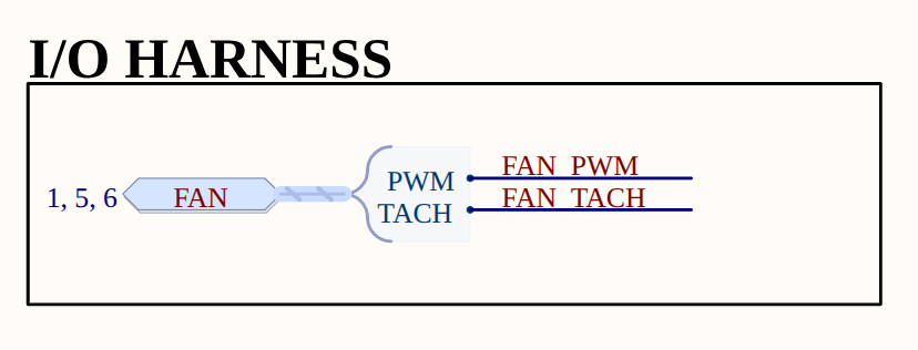
In terms of the provided images, I would suggest reviewing the schematic for the fan connections on the custom carrier board (tachinputjetson) and comparing it to the schematic for the fan connections on the different compute module that works fine.

Additionally, I would like to point out that the provided information mentions that the same fan works fine on identical Tach Input circuitry going into a different compute module on the same board. This suggests that the issue may be specific to the Jetson AGX Orin module or its configuration.

In comparison to the other provided information, I would like to note that the issue seems to be specific to the Jetson AGX Orin module and its configuration, and not related to the thermal zones, OC limits, or throttling levels mentioned in the other text.

It’s also worth noting that the provided information mentions that the fan is 12V, but the voltage levels are shifted as necessary. This could be a potential cause of the issue, and it may be worth investigating the voltage level shifting circuitry to ensure that it is not causing the problem.

Overall, I would suggest a thorough review of the device tree configuration, pinmux configuration, and schematic of the fan connections to identify the root cause of the issue.

*** Please give the thumbs up if you get answers you like. Or provide feedback to help us improve the answer. ***

Hello sperry-humanoid,

The FAN_TACH signal defaults to enable a 50k pull down at reset. In the Jetson AGX Orin Series Pinmux row 94 for FAN_TACH, please change the “Req. Initial State” (column AU) to “Z”. By default it is blank so the pull down remains enabled if you do not change the initial state entry.

@ChrisB_NV I’ve tried making this change in the pinmux spreadsheet. The output dtsi files don’t change whether “Req. Initial State” is Z or blank. (Verified with diff command. All 3 output files are identical).

I believe the relevant section of the pinmux file (Orin-jetson_agx_orin-pinmux.dtsi) is this, which I am already using:

			soc_gpio29_pq2 {
				nvidia,pins = "soc_gpio29_pq2";
				nvidia,function = "nv";
				nvidia,pull = <TEGRA_PIN_PULL_NONE>;
				nvidia,tristate = <TEGRA_PIN_ENABLE>;
				nvidia,enable-input = <TEGRA_PIN_ENABLE>;
				nvidia,io-high-voltage = <TEGRA_PIN_DISABLE>;
				nvidia,lpdr = <TEGRA_PIN_DISABLE>;
			};

That pin configuration looks correct.

Can you please share the circuit level shifting the TACH signal down to 1.8V for the input to Orin?

The circuit is shown in the original post (TACH INPUT diagram). The signal from the fan enters at FAN_TACH_IN, and is voltage divided (twice) to get the FAN_TACH signal, which goes directly to E54 on the Jetson.

Is this still an issue to support? Any result can be shared?

Still no solution found.

Can of course write my own fan speed controller based on manual temperature readings, but this is not an ideal solution.

I’ve had a change to do a little more experimentation with this.

I applied the following overlay to add a pullup resistor to the tachometer input.

/dts-v1/;
/plugin/;

/ {
    overlay-name = "AGX-Orin-Fan-PullUp-Fix";

    fragment@0 {
        target = <&pinmux>;
        __overlay__ {
            pinctrl-names = "default";
            pinctrl-0 = <&pinmux_default>;

            pinmux_default: common {
                soc_gpio29_pq2 {
                    nvidia,pins = "soc_gpio29_pq2";
                    nvidia,function = "nv";
                    nvidia,pull = <2>;           /* 2 = TEGRA_PIN_PULL_UP */
                    nvidia,tristate = <1>;       /* 1 = TEGRA_PIN_ENABLE */
                    nvidia,enable-input = <1>;   /* 1 = TEGRA_PIN_ENABLE */
                    nvidia,io-high-voltage = <0>;/* 0 = TEGRA_PIN_DISABLE */
                    nvidia,lpdr = <0>;           /* 0 = TEGRA_PIN_DISABLE */
                };
            };
        };
    };
};

Probing the tachometer pin at the fan connector (before the voltage divider circuitry I mentioned in the first post), I get this noisy signal (without the pullup resistor).

Once the pull up overlay is applied, we get a much more substantial signal. These images show during boot (clean square wave ~70mV) and after boot (noisier square wave ~110mV).

For reference, here is the signal I get with the fan connected to the other compute module, which can read the fan tachometer fine (noisy square wave ~300mV).

A further update - found the issue and solution. On closer inspection of the carrier board, it turns out that R366B from the TACH INPUT circuit was not populated. As a result, the fan tach signal wasn’t being pulled up to 12V before the division down to ~1.8V, meaning the signal never went high enough to register on the input pin.

Solution was either to populate this resistor, or remove R364B and add the internal pullup with the overlay I posted earlier.