Hi there,
I’d like to use my trained neural network to apply it to a similar but different geometry. I’ve read about the eval() mode, but I need more information.
I know there are already few basic topics in this forum as well as the three fin example, but which instances does my skript need if I want to use a different geometry instead of another parameterset?
Do I need to define all my Constraints just like when training a model? What do I need to change apart from my geometry?
Basically how should my basic script look like? Which instances are mandatory? Or is this even possible?
A fast forward help would be much appreciated.
Many thanks in advance.
Hi @jflatter
If you want to change the geometry, then its just updating the geometry object that is fed into the constraints/inferencers/monitors. E.g. The (point wise) constraints view the geometry as this point generator, thats it. For example, you could define a circle for the heat_sink geometry used here and the solver should then just sample training points based on this new shape.
Its the same deal for pointwise inferencers. For inference (with a trained model), just define your new geometry (assuming its of the same dimension as your previous geometry) and provide it to a pointwise inferencer thats added to a solver. Assuming all other input variables are provided and the symbolic graph can unroll you should be good to go to call solver.eval().
Hi @ngeneva
Thank you for your reply.
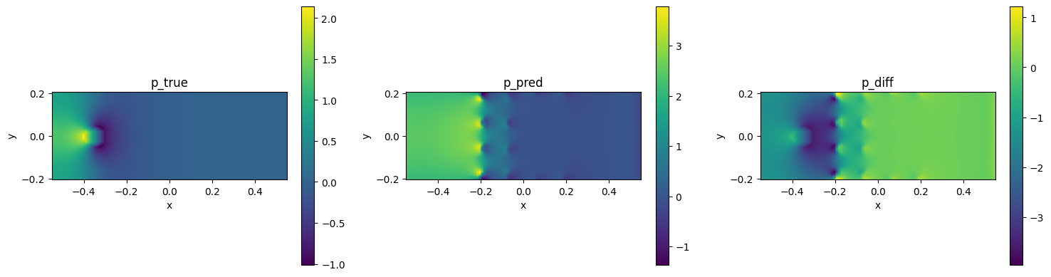
I tried applying a trained model to a different geometry (different size and less obstacles in the channel). All I used was the pointwise validator (for openfoam reference) and I changed my mode to eval(), just like you said. I defined the new geometry including all boundary conditions just like the one I trained on.
However, Modulus just seems to resample the trained interior onto the new domain, without “calculating” any different behavior. I attached a picture for better understanding. There you can see that Modulus doesn’t take the new obstacle into account at all. Where is my mistake?
Many thanks in advance.
Hi @jflatter
Hmmm,
I’m assuming your model has some sort of parameter / input that would reflect the new geometry (i.e. its not just x or y) otherwise your network will have no idea if anything has changed since its point wise.
Consider generating a VTK point cloud output by changing the ouput format in the config (example here). Then display that VTP file in Paraview to see what points were actually sampled and if that reflects your geometry.
Its hard to tell from these matplotlib plots since it actually interpolates the unstructured points onto a grid under the hood for these images.
Hi @ngeneva
Thank you for your help.
I applied a totally different geometry with different shape, which wasn’t parameterized which will be the problem I guess.
I’ve now defined a new geometry with a parameter range for a cylinder radius. How can I change the radius for evaluation? Just change the range parameter to a fixed value and run on eval() mode?
This is my code snippet:
cylinder_radius = Parameter("cylinder_radius")
param_range = (0.01, 0.06)
pr = Parameterization({cylinder_radius: param_range})
cylinder = Circle(cylinder_center, cylinder_radius, parameterization=pr)
Thanks in advance.
Hi @jflatter
Correct, on the construction of the constraints/inferencers/validators/monitors the (modified) geometry is sampled to generate the point cloud. So in your inference script just change your parameterization from a range to a number. Have a look at this sample script:
from modulus.sym.geometry.primitives_2d import Circle
from modulus.sym.utils.io.vtk import var_to_polyvtk
from modulus.sym.geometry.parameterization import Parameterization, Parameter

if __name__ == "__main__":
    # make plate with parameterized hole
    # make parameterized primitives
    param_range = (0.01, 0.06)
    cylinder_radius = Parameter("cylinder_radius")
    pr = Parameterization({cylinder_radius: param_range})
    cylinder = Circle(center=(0, 0), radius=cylinder_radius, parameterization=pr)

    # This is done inside a constraint on construction (unless continous sampling)
    s = cylinder.sample_interior(nr_points=100000)
    var_to_polyvtk(s, "parameterized_interior")

    # Fix parameterization
    pr = Parameterization({cylinder_radius: 0.02})
    cylinder = Circle(center=(0, 0), radius=cylinder_radius, parameterization=pr)
    s = cylinder.sample_interior(nr_points=100000)
    var_to_polyvtk(s, "fixed_interior")
The parameterized sample uses points between radius 0.01 to 0.06.
The fixed one has all samples uniformly in a radius of 0.02
1 Like