Distortion correction model using vpi interface on agx equipment;
version:
nvidia@localhost:~/xxw/df_gtest/df_src_test$ head -n 1 /etc/nv_tegra_release
R32 (release), REVISION: 4.3, GCID: 21589087, BOARD: t186ref, EABI: aarch64, DATE: Fri Jun 26 04:34:27 UTC 2020
vpi 0.4.4
There is a demo for the fisheye model, but no demo for the polynomial model. The customer wants to compare these two models.
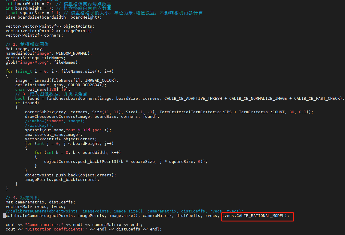
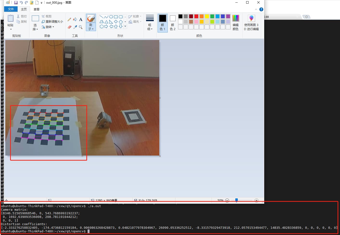
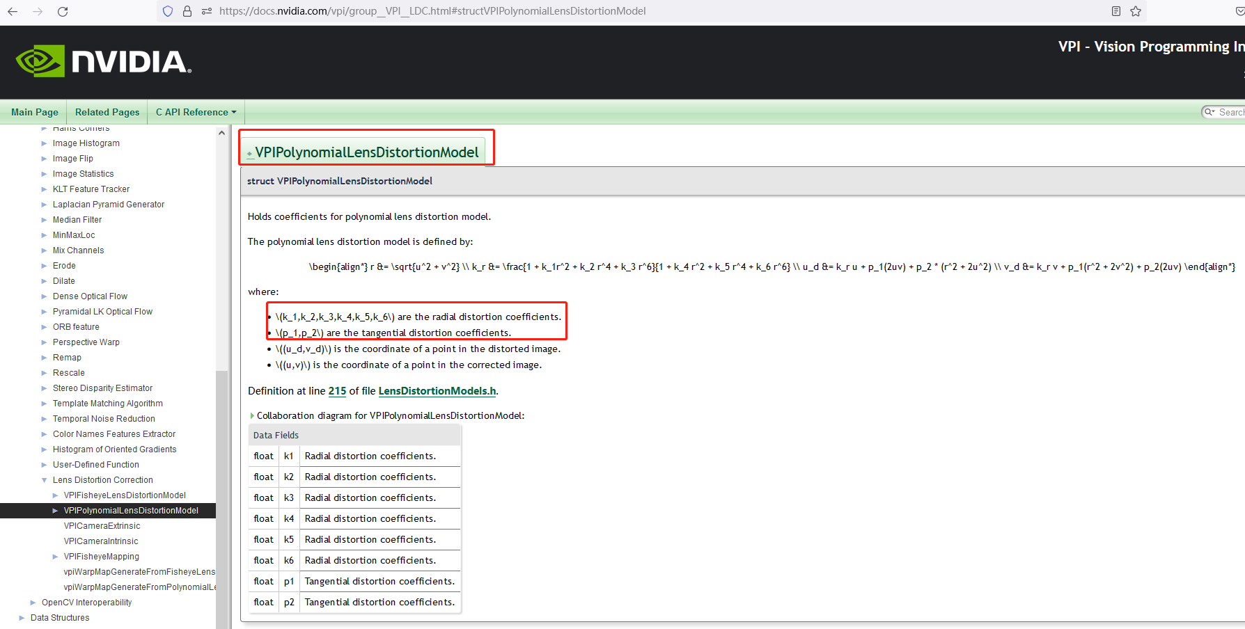
The polynomial model requires k1,k2,k3,k4,k5,k6 and p1,p2, which can be obtained by using opencv’s CALIB_RATIONAL_MODEL, but it seems that the relevant parameters obtained by this method are brought into the polynomial model interface of vpi, and the image obtained is not correct.
How should the polynomial model of vpi interface be used correctly?
yes,There is only the fisheye model and only 4 distortion coefficients.
How should the polynomial model of vpi interface be used correctly?
How to obtain the distortion coefficient of polynomial model?
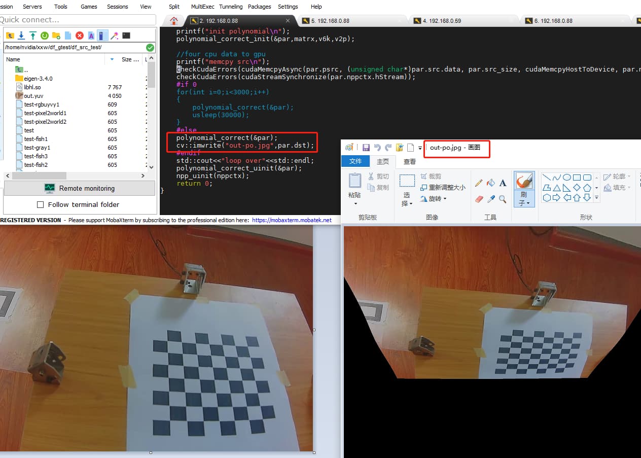
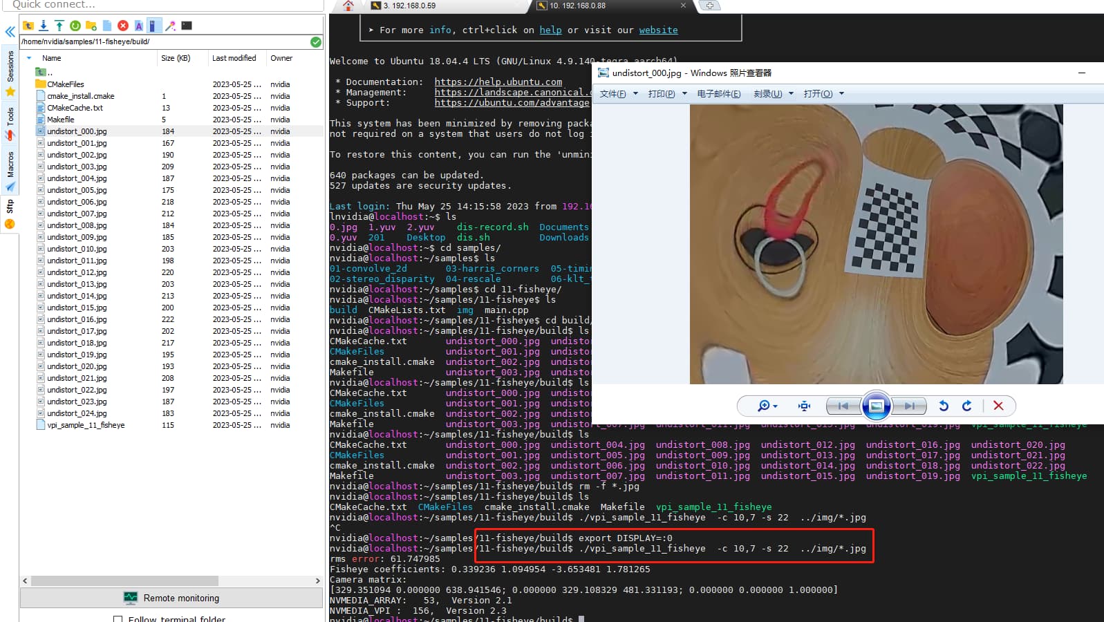
Thank you, this problem has been solved. It is caused by the large error of 8 parameters calculated by opencv because there are only 4 calibration pictures. The number of calibration images increased to 31, and the parameters calculated by opencv were imported into the polynomial model with correct distortion correction. However, when the fisheye model uses the data of the camera, the calibration checkerboard is 8x8,the data after distortion correction is not correct. I wonder why?The same program uses the official own pictures and self-collected camera pictures have a very big difference. Official Checkerboard 10x7; The company uses a checkerboard 8x8
The following can be added to the flag parameter of the official demo to solve this problem
    // VPI currently doesn't support skew parameter on camera matrix, make sure
    // calibration process fixes it to 0.
    int flags = cv::fisheye::CALIB_FIX_SKEW;   //official par
    //add flags  par