please also examine your pin configuration, which has definition in the device tree.
you may disassembler the dtb file into text file for checking,
for example, $ dtc -I dtb -O dts -o output.txt tegra210-p3448-0000-p3449-0000-a02.dtb
thanks
What is the location of tegra210-p3448-0000-p3449-0000-a02.dtb?
I run your command and got:
dtc -I dtb -O dts -o output.txt tegra210-p3448-0000-p3449-0000-a02.dtb
FATAL ERROR: Couldn't open "tegra210-p3448-0000-p3449-0000-a02.dtb": No such file or directory
I have not configured or build kernel, I only run jetson-io.py - it’s not enough?
according to pinmux spreadsheets, pin-32, GPIO07 and pin-33, GPIO13 were configure as GPIO by default.
please help to narrow down the issue,
please also have an alternative ways to have customization besides using Jetson-IO tools.
you may also refer to Pinmux Changes session to customize the pinmux spreadsheet.
thanks
Have you read my messages?
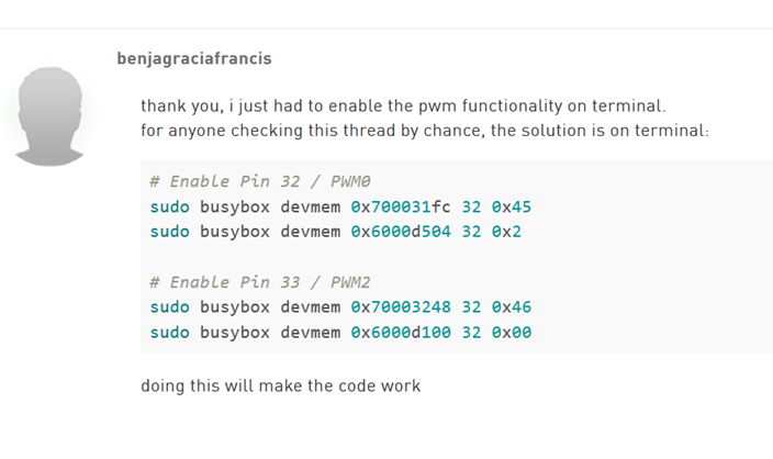
In the first message i wrote the exact steps, i export pwmchip0 echo 0 > /sys/class/pwm/pwmchip0/export
Command /sys/kernel/debug/pwm shows debug info about everything. I am not using 70110000. I am using pwmchip0, can you see the lines:
there’s limits based on controller’s clock source and the frequency and pulse divisor values.
while there’s no messages means the channel and the settings has applied successfully.
could you please modify the period and dutycycle as below for confirmation?
for example,
Connected oscilloscope to PIN32 and GND.
No signal. Random noise.
@libsong
Could you please provide a step by step instruction that worked for you? May be you used some other commands in combination? Or may be you used some external power? Please tell more details, can’t get it work :(