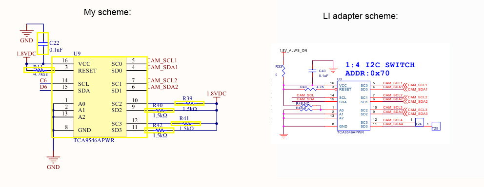
There is the same tca9546a switch too.
If the LI adapter installed on Nvidia dev board then the switch detected on i2c bus 6 with address 0x70 with 4 child channels:
Kernel.log
pca954x 6-0070: pca954x_probe: forcing device bus number, start 30.
pca954x 6-0070: device detect skipped.
regulator_get() failed for (6-0070,vcc-pullup), -19
pca954x 6-0070: vcc-pullup regulator not found
i2c i2c-6: Added multiplexed i2c bus 30
i2c i2c-6: Added multiplexed i2c bus 31
i2c i2c-6: Added multiplexed i2c bus 32
i2c i2c-6: Added multiplexed i2c bus 33
pca954x 6-0070: registered 4 multiplexed busses for I2C switch pca9546
But if the same TX1 module installed on my carrier board then the switch doesn’t work:
Kernel.log
pca954x 6-0070: lp_reg get fail
pca954x: probe of 6-0070 failed with error -12
The switch installed on carrier with the same address pins and with pull-up resisters 1.8v as on the LI adapter board.
Where is my mistake?
The same schematics, the same switch, the same TX1 module with the same software, but doesn’t work.
All power i am taking from my 12v source and then 1.8v regulator TPS62131RGTT.
That described case is when the cameras not connected.
All switch output sda/scl pulled up to 1.8v with 1.5kohm. In my and in LI schemes.
I don’t see VIN_PWR_BAD# or CARRIER_PWR_ON signals in your schematic. Please check the power on sequence in OEM DG to find out the violations, also there is timing value request in the following table.
I understand that my power scheme is not good. And after 12v TX1 poweron signal i shoud powerup EN->5.0 → EN->3.3 → EN-> 1.8 → reset…
Cause it is my intermediate prototype.
And i will fix it.
But all my devices 2xi2c(including switch), usb, sd, spi, uart are online now.
The question is about switch and i2c nodes producing.
Sorry for my importunity.
I think we met the same problem. @vsw, did you fix your problem?
Some differences are:
I made my own carrier board for TX2. The tca9546a switch on Tx2 i2c-2 bus, and was detected on address 0x70.
There is a 24c04 eeprom chip connect one of the tca9546a child channel, with slave-addr 0x57. I opened all the child channels, but still cannot be detected.
I use i2ctools, and c program, the results are same. In the c program, when I write to 24c04, return “Remote I/O error”.
But the parallel connection beteen tca9546a and 24c04 can work fine. Here is the log with i2ctools. The tool cannot detect, read, and write the eeprom.