Hello, I would like to know how to connect some relays to the GPIO outputs of my Jetson Orin Nano to perform some functions. I have seen that the Jetson Orin Nano board does not have enough output power from the terminals to act directly on a relay as it is a digital output. Is there a way or someone could help me, thank you all.
Look here:
Thanks, I’m going to try this board.
I tried this and it doesn’t work, I don’t really understand why it doesn’t work??? 3 Channel Relay Expansion Board for NVIDIA Jetson Nano B01/2GB Optocoupler Isolation with GPIO Header for Jetson Nano
The relay module is controlled by three GPIOs. Did you verify that you are actually able to control these pins and set them to high or low with a multimeter or oscilloscope or any other means of measuring the pin voltage. The relay board should not be present for the first tests.
After successful control of these pins without the relay board try the same with the relay board connected. Measure the voltages on the gpio pins as well and make sure you can set each pin to high and to low and you can measure the high and low states.
Be aware that you can’t use the instructions for Raspbery Pi . The 40-pin header is electrically similar to the one on a Pi, but the Linux GPIO numbers are different.
Thanks for the help. I’m going to try an example from JatsonHacks to turn on an LED, changing the LED for a relay. Currently, to have an output indication of the Jetson Orin Nano, I use a Keyestudio LED, who are fed. It has signal input, positive and negative power and so far it works well.
Hello everyone. I have good news about activating relays with the Jetson Orin Nano outputs. As I mentioned in the last post, I made a JetsonHacks setup, where with a transistor and a couple of resistors, an LED could be activated without extra power. Now, the idea is to activate a relay, to have an output that can be used with other means. Use a relay module that I have with Arduino. They are powered relays, they have a +, - input and in this case 2 signals to activate the relays (2). Connect the LED output to the signal input of (1) relay and the relay module with power supply and that’s it. I listened to you (fchkjwlsq) and checked the outputs with an oscilloscope, 2.40v comes out of pin (12), it is very little, it is almost impossible to use if not digitally. I hope I can help someone like they did to me.


The problem is that the carrier boards have weak 1.8V to 3.3V level shifters that can easily be disturbed.
A solution is to use a buffer (e.g. 74LVC541A, 8 channels). These are LVCMOS buffers that can delivers 24mA of output current with minimal load to the inputs.
Or use a dual-supply level translator 74LVC8T245 (8 channels) where one side is driven with 3.3V and the other side is 5V. This chip is also capable of delivering 24mA on each pin for 3.3V or 32mA for 5V.
Two fundamental rules for digital logic:
- always have a 100nF ceramic cap between each VVC/GND pair with wires/traces as short als possible. (each mm counts)
- Never leave any digital inputs open. Always pull them to low or high.
Hello, good morning fchkjwlsq. Thank you very much for your help and advice. I also tried this board, but the Jetson Orin Nano output does not have enough voltage to activate the Mosfets. (see photo of the plate). At this moment I am drawing with EasyEDA a prototype board (PCB) with the diagram of the first photo that I uploaded previously, at the moment it is what has given me the best result. If you look at the photo of the oscilloscope, you will see that there is only 2.40v under load, but without load 3.36+/-v. I’m going to try the transistor right now and will continue investigating later. The board in the photo does not work directly, there is some light on the signal indicator LED and it does not work, if I do it with the transistor it works perfectly. We will be in touch, thank you.


Your 2N2222 is not a FET but a BJT. While FETs require a voltage for activation BJT require a current for activation.
FET inputs (like the ones in the 74LVC541A and the 74LVC8T245) have a very high impedance and act as a small capacitor in the pF range to the output driver of the Devkit’s outputs). This will solve your problem.
clear
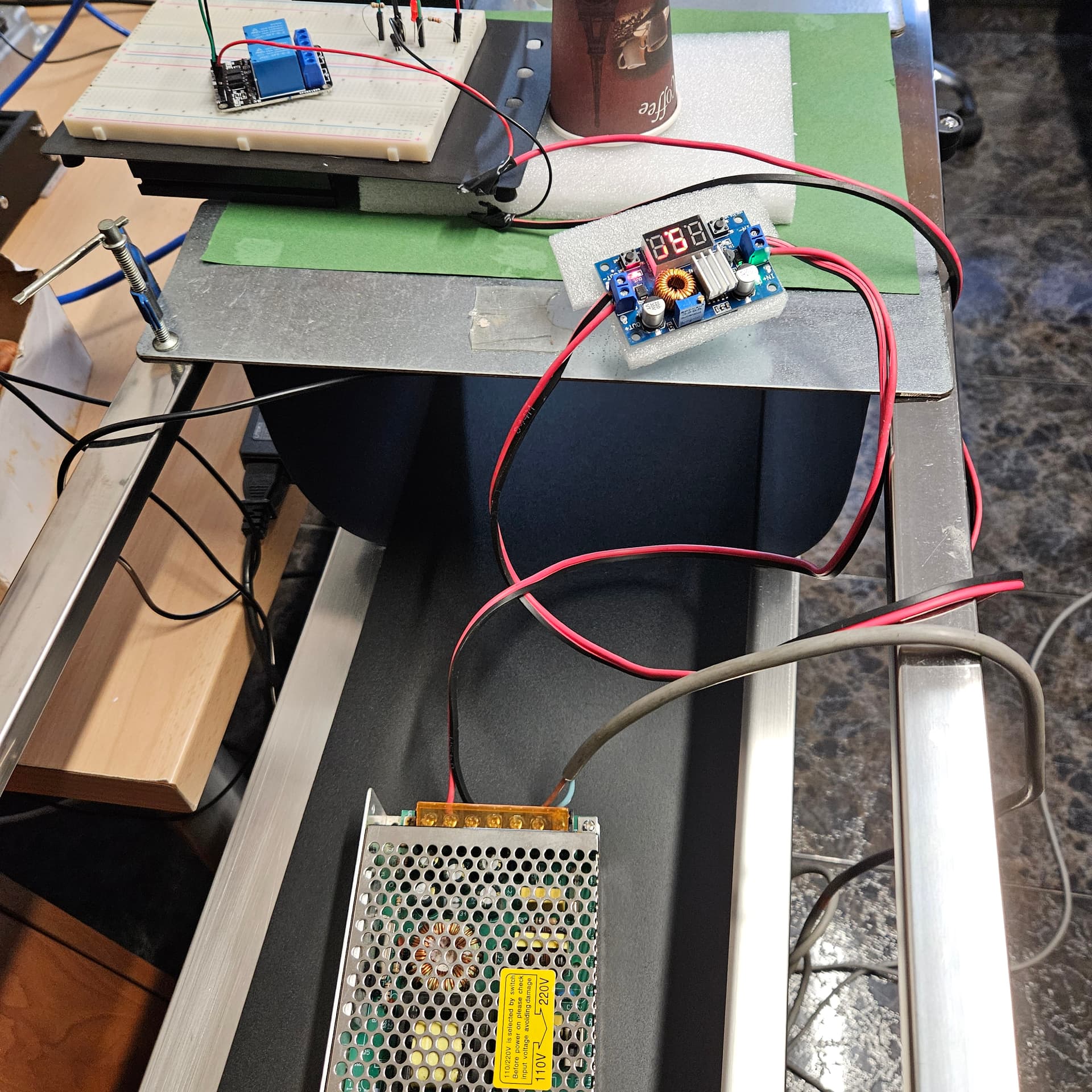
Hi Frank. I have made a small PCB to be able to place the components more securely. So far it has worked perfectly. I’m waiting for the board you recommended from Raspberry so I can try it, in fact having built a pcb for an output, I don’t think it will take long to make a more efficient pcb design in every way. Personal note: I am not a programmer nor an electronics engineer, I am eagerly self-taught. I am currently working on a small Jetson-Inference project to manufacture or at least try a nut classification machine (Hazelnuts), so far everything has gone very well, but now I lacked power for the electromechanical actuator. Thanks again for your help, we will be in touch. I’ll upload some photos for everyone and in case someone can help.


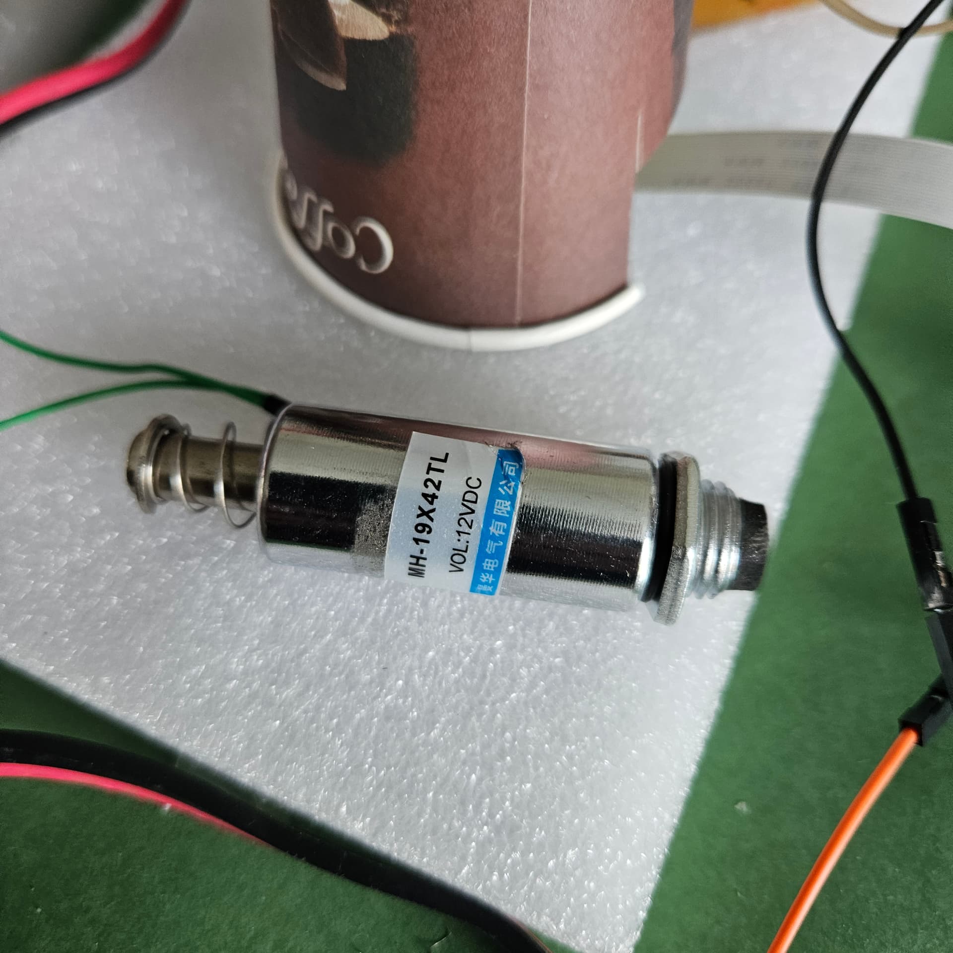
Hello everyone,. I have been doing more tests with my Jetson Orin nano and the connection with relays, and at the moment the only way for this to work (for the relay(s) to be activated) is by using the small auxiliary board with a transistor and a couple of resistors, (The original schematic is from JetsonHacks) the only thing I have done was add an output to activate a relay and make a small PCB. I have tried without success a relay powered with +, - and Keyestudio signal input just like the LED seen in the photo. I also just tested the Waveshare 8-relay board for Raspberry and it doesn’t work when connected directly to the Jetson Orin Nano either. Checked with the oscilloscope, the Jetson Orin Nano has a load voltage output of 2.40v (does mine have any problems?) and all the boards or relays need a minimum of 3v for activation. Now I will spend some time trying to make a board for 10 relays or outputs, when I see some results I will publish them. Everything I upload here is to help those who are in need, like others did with me. Greetings to all.
I made a small improved PCB.


When you connect the Jetson Orin Nano board to the Waveshare pins where the Raspberry board would go, it does nothing. But if I connect it through the PCB with the transistor and to the inputs, it works.
Hi, you can read below doc first.
Jetson Nano Developer Kit 40-Pin Expansion Header GPIO Usage Considerations Applications Note
Hello Trumany, thanks for the information. What left me a little confused is that I could drive a powered Keyestudio LED and I couldn’t drive some relays that also have power and an optocoupler that I use with Arduino or Raspberry. As you may have read previously, I followed a JetsonHacks setup to turn on an LED and modified something to activate a relay, it was a success. Currently I have solved the problem with a board designed by me in which I have 4 inputs and I can activate 4 outputs, which I will upload soon in case they can help someone or someone can suggest some improvement. Greetings to all.
Note: It is also true that I had not read the information you gave me :(
Hello everyone. Today I am going to upload my small project to be able to activate some relays (4 at the moment) that have an optocoupler and are powered directly from the PCB and which in turn is powered by an external 5V source. At the moment it works very well for me, except for the cables to make the connections between the Nvidia Jetson Orin Nano and the pcb described here. The cables have given me some scares, because they are not of the necessary quality to guarantee good contact with the pins. Powering the PCB externally with 5v has been to avoid having to carry consumption that could be dangerous for the Nvidia Jetson Orin Nano. The only connections between the PCB and Nvidia are the signal cables and a ground cable. (Be careful that the mass does not fail, this is what I was referring to before with the scares. I will upload photos and the files that I have generated, if you edit them. I am open to improvements and constructive observations. I hope to be able to help the that he needs, like others did with me.

PCB_PCB_4sortides copy2_2024-06-04.pdf (57.8 KB)


Hello everyone. I’m working on some small improvements with more outputs and some protection on the signal input from the Nvidia Jetson Orin Nano.
Hi Turbotronc! Are you using Jetpack 6?
No, I use version 5.1.2 because the camera I have to capture in Jetson-inference does not work with other versions, the manufacturer e-con Sytems has not yet updated the drivers, greetings