我使用orin nano核心版,自己的底板,适配sc1336的sensor,分别接到csi0和csi1上,都是2lane的,现在能够识别出video0,但是我使用
strace -e trace=ioctl,write,read v4l2-ctl -d /dev/video0 --set-fmt-video=width=1280,height=720,pixelformat=BG10 --stream-mmap --stream-count=1 --stream-to=frame.raw
抓图系统就卡死,输入不了东西
附件是我的设备树,驱动 和dmesg的信息
下面是vedio0的信息
media-ctl -p
Media controller API version 5.15.148
Media device information
driver tegra-camrtc-ca
model NVIDIA Tegra Video Input Device
serial
bus info
hw revision 0x3
driver version 5.15.148
Device topology
-
entity 1: 13e00000.host1x:nvcsi@15a00000- (2 pads, 2 links)
type V4L2 subdev subtype Unknown flags 0
device node name /dev/v4l-subdev0
pad0: Sink
← “sc1336 0-0032”:0 [ENABLED]
pad1: Source
→ “vi-output, sc1336 0-0032”:0 [ENABLED] -
entity 4: 13e00000.host1x:nvcsi@15a00000- (2 pads, 0 link)
type V4L2 subdev subtype Unknown flags 0
device node name /dev/v4l-subdev1
pad0: Sink
pad1: Source -
entity 7: sc1336 0-0032 (1 pad, 1 link)
type V4L2 subdev subtype Sensor flags 0
device node name /dev/v4l-subdev2
pad0: Source
[fmt:SBGGR10_1X10/1280x720@1/30 field:none colorspace:srgb]
→ “13e00000.host1x:nvcsi@15a00000-”:0 [ENABLED] -
entity 9: vi-output, sc1336 0-0032 (1 pad, 1 link)
type Node subtype V4L flags 0
device node name /dev/video0
pad0: Sink
← “13e00000.host1x:nvcsi@15a00000-”:1 [ENABLED]media-ctl -p
v4l2-ctl -d /dev/video0 --all
Media controller API version 5.15.148Media device information
driver tegra-camrtc-ca
model NVIDIA Tegra Video Input Device
serial
bus info
hw revision 0x3
driver version 5.15.148Device topology
-
entity 1: 13e00000.host1x:nvcsi@15a00000- (2 pads, 2 links)
type V4L2 subdev subtype Unknown flags 0
device node name /dev/v4l-subdev0
pad0: Sink
← “sc1336 0-0032”:0 [ENABLED]
pad1: Source
→ “vi-output, sc1336 0-0032”:0 [ENABLED] -
entity 4: 13e00000.host1x:nvcsi@15a00000- (2 pads, 0 link)
type V4L2 subdev subtype Unknown flags 0
device node name /dev/v4l-subdev1
pad0: Sink
pad1: Source -
entity 7: sc1336 0-0032 (1 pad, 1 link)
type V4L2 subdev subtype Sensor flags 0
device node name /dev/v4l-subdev2
pad0: Source
[fmt:SBGGR10_1X10/1280x720@1/30 field:none colorspace:srgb]
→ “13e00000.host1x:nvcsi@15a00000-”:0 [ENABLED] -
entity 9: vi-output, sc1336 0-0032 (1 pad, 1 link)
type Node subtype V4L flags 0
device node name /dev/video0
pad0: Sink
← “13e00000.host1x:nvcsi@15a00000-”:1 [ENABLED]
Driver Info:
Driver name : tegra-video
Card type : vi-output, sc1336 0-0032
Bus info : platform:tegra-capture-vi:1
Driver version : 5.15.148
Capabilities : 0x84200001
Video Capture
Streaming
Extended Pix Format
Device Capabilities
Device Caps : 0x04200001
Video Capture
Streaming
Extended Pix Format
Media Driver Info:
Driver name : tegra-camrtc-ca
Model : NVIDIA Tegra Video Input Device
Serial :
Bus info :
Media version : 5.15.148
Hardware revision: 0x00000003 (3)
Driver version : 5.15.148
Interface Info:
ID : 0x0300000b
Type : V4L Video
Entity Info:
ID : 0x00000009 (9)
Name : vi-output, sc1336 0-0032
Function : V4L2 I/O
Pad 0x0100000a : 0: Sink
Link 0x0200000f: from remote pad 0x1000003 of entity ‘13e00000.host1x:nvcsi@15a00000-’ (Unknown sub-device (0002000a)): Data, Enabled
Priority: 2
Video input : 0 (Camera 1: ok)
Format Video Capture:
Width/Height : 1280/720
Pixel Format : ‘BG10’ (10-bit Bayer BGBG/GRGR)
Field : None
Bytes per Line : 2560
Size Image : 1843200
Colorspace : sRGB
Transfer Function : Default (maps to sRGB)
YCbCr/HSV Encoding: Default (maps to ITU-R 601)
Quantization : Default (maps to Full Range)
Flags :
Streaming Parameters Video Capture:
Capabilities : timeperframe
Frames per second: 30.000 (30/1)
Read buffers : 0Camera Controls
group_hold 0x009a2003 (bool) : default=0 value=0 flags=execute-on-write sensor_mode 0x009a2008 (int64) : min=0 max=1 step=1 default=0 value=0 flags=slider gain 0x009a2009 (int64) : min=16 max=357 step=1 default=16 value=16 flags=slider exposure 0x009a200a (int64) : min=13 max=683710 step=1 default=2495 value=13 flags=slider frame_rate 0x009a200b (int64) : min=2000000 max=30000000 step=1 default=30000000 value=2000000 flags=slider sensor_configuration 0x009a2032 (u32) : min=0 max=4294967295 step=1 default=0 dims=[22] flags=read-only, volatile, has-payload sensor_mode_i2c_packet 0x009a2033 (u32) : min=0 max=4294967295 step=1 default=0 dims=[1026] flags=read-only, volatile, has-payload sensor_control_i2c_packet 0x009a2034 (u32) : min=0 max=4294967295 step=1 default=0 dims=[1026] flags=read-only, volatile, has-payload bypass_mode 0x009a2064 (intmenu): min=0 max=1 default=0 value=0 (0 0x0) 0: 0 (0x0) 1: 1 (0x1) override_enable 0x009a2065 (intmenu): min=0 max=1 default=0 value=0 (0 0x0) 0: 0 (0x0) 1: 1 (0x1) height_align 0x009a2066 (int) : min=1 max=16 step=1 default=1 value=1 size_align 0x009a2067 (intmenu): min=0 max=2 default=0 value=0 (1 0x1) 0: 1 (0x1) 1: 65536 (0x10000) 2: 131072 (0x20000) write_isp_format 0x009a2068 (int) : min=1 max=1 step=1 default=1 value=1 sensor_signal_properties 0x009a2069 (u32) : min=0 max=4294967295 step=1 default=0 dims=[30][18] flags=read-only, has-payload sensor_image_properties 0x009a206a (u32) : min=0 max=4294967295 step=1 default=0 dims=[30][16] flags=read-only, has-payload sensor_control_properties 0x009a206b (u32) : min=0 max=4294967295 step=1 default=0 dims=[30][36] flags=read-only, has-payload sensor_dv_timings 0x009a206c (u32) : min=0 max=4294967295 step=1 default=0 dims=[30][16] flags=read-only, has-payload low_latency_mode 0x009a206d (bool) : default=0 value=0 preferred_stride 0x009a206e (int) : min=0 max=65535 step=1 default=0 value=0 override_capture_timeout_ms 0x009a206f (int) : min=-1 max=2147483647 step=1 default=2500 value=2500 sensor_modes 0x009a2082 (int) : min=0 max=30 step=1 default=30 value=1 flags=read-only -
sdk36.4.4,

hello zhouleicheng,
please revise the device tree CSI/VI port bindings.
according to the CAM schematic, you’ve 1st camera connected to CSI-0 (i.e. CSI-A), and 2nd camera connected to CSI-1 (i.e. CSI-B).
for instance,
	tegra-capture-vi {
			port@1 {
				rbpcv3_sc1336_vi_in1: endpoint {
					port-index = <2>;  <== it should be 0.
					bus-width = <2>;
					remote-endpoint = <&rbpcv3_sc1336_csi_out1>;
	bus@0 {
		host1x@13e00000 {
			nvcsi@15a00000 {
				channel@1 {
					ports {
						port@0 {
							rbpcv3_sc1336_csi_in1: endpoint@2 {
								port-index = <2>; <== it should be 0.
								bus-width = <2>;
								remote-endpoint = <&rbpcv3_sc1336_out1>;
			rbpcv3_sc1336_a@30 {
				mode0 {
					tegra_sinterface = "serial_a";
				...
				ports {
					port@0 {
						rbpcv3_sc1336_out1: endpoint {
							status = "okay";
							port-index = <2>;   <== it should be 0.
							bus-width = <2>;
besides.. please refer to Jetson Orin NX Series and Orin Nano Series Design Guide.
you should see-also [Figure 10-1. CSI 2-Lane Connection Options], CSI_0_D1 and CSI_1_D0 have P/N swapped on the module.
please also have device tree property settings, lane_polarity to configure polarity swap.
这是我最新的设备树
有一个地方我没有理解
我的rgb 0x32接在csi0上面,ir 0x30接在csi1上面
为什么0x30的配置不是port-index = <2>;,而是port-index = <0>;,index不应该是从0开始吗?
我现在遇到的问题是抓图报错
sc1336 0-0032: sc1336_power_on: power on
[ 84.578882] sc1336 0-0032: sc1336_power_on: reset GPIO=397, setting to 0 (reset)
[ 84.725640] sc1336 0-0032: sc1336_power_on: reset GPIO=397, setting to 1 (release)
[ 84.750672] sc1336 0-0032: sc1336_power_on: reset GPIO released, sensor should be ready
[ 84.764206] sc1336: sc1336_set_mode: ENTRY, s_data->mode=0
[ 84.764212] sc1336 0-0032: sc1336_set_mode: ENTRY, s_data->mode=0
[ 84.764216] sc1336 0-0032: sc1336_set_mode: about to write mode table for mode_index=0
[ 84.764219] sc1336: sc1336_write_table: ENTRY
[ 84.764222] sc1336 0-0032: sc1336_write_table: ENTRY
[ 84.764225] sc1336 0-0032: sc1336_write_table: reg[0] = 0x0103 = 0x01
[ 84.764230] sc1336 0-0032: sc1336_write_table: reg[1] = 0x0100 = 0x00
[ 84.764234] sc1336 0-0032: sc1336_write_table: reg[2] = 0x36e9 = 0x80
[ 84.764238] sc1336 0-0032: sc1336_write_table: reg[3] = 0x37f9 = 0x80
[ 84.764241] sc1336 0-0032: sc1336_write_table: reg[4] = 0x301f = 0x18
[ 84.764246] sc1336 0-0032: sc1336_write_table: writing table with 202 registers (showing first 5)
[ 84.764250] sc1336 0-0032: sc1336_write_table: about to call regmap_util_write_table_8
[ 84.793144] sc1336 0-0032: sc1336_write_table: table written successfully - EXIT
[ 84.793153] sc1336 0-0032: sc1336_set_mode: mode set successfully - EXIT
[ 84.793166] sc1336: sc1336_start_streaming: ENTRY
[ 84.793168] sc1336 0-0032: sc1336_start_streaming: ENTRY
[ 84.793171] sc1336 0-0032: sc1336_start_streaming: about to write start stream table
[ 84.793173] sc1336: sc1336_write_table: ENTRY
[ 84.793175] sc1336 0-0032: sc1336_write_table: ENTRY
[ 84.793178] sc1336 0-0032: sc1336_write_table: reg[0] = 0x0100 = 0x01
[ 84.793183] sc1336 0-0032: sc1336_write_table: reg[1] = 0x0000 = 0x00
[ 84.793187] sc1336 0-0032: sc1336_write_table: writing table with 2 registers (showing first 5)
[ 84.793189] sc1336 0-0032: sc1336_write_table: about to call regmap_util_write_table_8
[ 84.794055] sc1336 0-0032: sc1336_write_table: table written successfully - EXIT
[ 84.854085] sc1336 0-0032: sc1336_start_streaming: waited 50ms for sensor to start outputting data (fallback)
[ 84.854093] sc1336 0-0032: sc1336_start_streaming: stream started successfully - EXIT
[ 87.269771] tegra-camrtc-capture-vi tegra-capture-vi: uncorr_err: request timed out after 2500 ms
[ 87.269793] tegra-camrtc-capture-vi tegra-capture-vi: err_rec: attempting to reset the capture channel
[ 87.270834] tegra-camrtc-capture-vi tegra-capture-vi: err_rec: successfully reset the capture channel
[ 89.829748] tegra-camrtc-capture-vi tegra-capture-vi: uncorr_err: request timed out after 2500 ms
[ 89.829769] tegra-camrtc-capture-vi tegra-capture-vi: err_rec: attempting to reset the capture channel
[ 89.830847] tegra-camrtc-capture-vi tegra-capture-vi: err_rec: successfully reset the capture channel
[ 92.357840] tegra-camrtc-capture-vi tegra-capture-vi: uncorr_err: request timed out after 2500 ms
[ 92.357856] tegra-camrtc-capture-vi tegra-capture-vi: err_rec: attempting to reset the capture channel
[ 92.358856] tegra-camrtc-capture-vi tegra-capture-vi: err_rec: successfully reset the capture channel
[ 92.358883] sc1336 0-0032: sc1336_stop_streaming:
[ 92.358888] sc1336: sc1336_write_table: ENTRY
[ 92.358890] sc1336 0-0032: sc1336_write_table: ENTRY
[ 92.358892] sc1336 0-0032: sc1336_write_table: reg[0] = 0x0100 = 0x00
[ 92.358896] sc1336 0-0032: sc1336_write_table: reg[1] = 0x0000 = 0x00
[ 92.358898] sc1336 0-0032: sc1336_write_table: reg[2] = 0x0103 = 0x01
[ 92.358901] sc1336 0-0032: sc1336_write_table: reg[3] = 0x0100 = 0x00
[ 92.358903] sc1336 0-0032: sc1336_write_table: reg[4] = 0x36e9 = 0x80
[ 92.358907] sc1336 0-0032: sc1336_write_table: writing table with 204 registers (showing first 5)
[ 92.358909] sc1336 0-0032: sc1336_write_table: about to call regmap_util_write_table_8
[ 92.389078] sc1336 0-0032: sc1336_write_table: table written successfully - EXIT
[ 92.391577] sc1336 0-0032: sc1336_power_off: power off
看样子是csi数据没有接收到
非常感谢您的解答
hello zhouleicheng,
please double check your port bindings.
I was point-out your device tree erroneous, (i.e. tegra234-camera-sc1336-dual.dtsi.log)
besides.. please add lane_polarity to configure polarity swap since Orin Nano has CSI0 D1 and CSI1 D0 P/N will always been swizzled for P/N.
hi ,jerryChang,
我已经按照您给的提示修改,但是还是报错
tegra-camrtc-capture-vi tegra-capture-vi: uncorr_err: request timed out after 2500 ms
[ 147.079077] tegra-camrtc-capture-vi tegra-capture-vi: err_rec: attempting to reset the capture channel
[ 147.080429] tegra-camrtc-capture-vi tegra-capture-vi: err_rec: successfully reset the capture channel
[ 149.636488] tegra-camrtc-capture-vi tegra-capture-vi: uncorr_err: request timed out after 2500 ms
[ 149.636513] tegra-camrtc-capture-vi tegra-capture-vi: err_rec: attempting to reset the capture channel
[ 149.637809] tegra-camrtc-capture-vi tegra-capture-vi: err_rec: successfully reset the capture channel
[ 152.194553] tegra-camrtc-capture-vi tegra-capture-vi: uncorr_err: request timed out after 2500 ms
[ 152.194583] tegra-camrtc-capture-vi tegra-capture-vi: err_rec: attempting to reset the capture channel


hello zhouleicheng,
your device tree settings still looks incorrect.
per your schematic, it should connected to CSI-A and CSI-B.
although it has port bindings maps to CSI-0/CSI-1. you’ve both of them for using CSI-A (i.e. tegra_sinterface = "serial_a").
		i2c@3160000 {
			rbpcv3_sc1336_a@32 {
				mode0 {
					tegra_sinterface = "serial_a";
				...
				ports {
					port@0 {
						rbpcv3_sc1336_out0: endpoint {
							port-index = <1>;
							bus-width = <2>;
							remote-endpoint = <&rbpcv3_sc1336_csi_in0>;
			rbpcv3_sc1336_a@30 {
				mode0 {
					tegra_sinterface = "serial_a";
				...
				ports {
					port@0 {
						rbpcv3_sc1336_out1: endpoint {
							port-index = <0>;
							bus-width = <2>;
							remote-endpoint = <&rbpcv3_sc1336_csi_in1>;
following above, I assume you’ve only single camera device detected and register to system, in other words, there’s only /dev/video0 created, right?
as you can see.. it’s capture timeout error has reported.
please refer to developer guide, Sensor Pixel Clock to review your clock rate settings, which must be set correctly to avoid potential issues.
FYI, I usually using sensor CSI lane output rate for calculation.
pixel_clk_hz = sensor data rate per lane (Mbps) * number of lanes / bits per pixel
besides..
you may give it another try with below commands to boost all the VI/CSI/ISP clocks for testing.
sudo su
echo 1 > /sys/kernel/debug/bpmp/debug/clk/vi/mrq_rate_locked
echo 1 > /sys/kernel/debug/bpmp/debug/clk/isp/mrq_rate_locked
echo 1 > /sys/kernel/debug/bpmp/debug/clk/nvcsi/mrq_rate_locked
echo 1 > /sys/kernel/debug/bpmp/debug/clk/emc/mrq_rate_locked
cat /sys/kernel/debug/bpmp/debug/clk/vi/max_rate |tee /sys/kernel/debug/bpmp/debug/clk/vi/rate
cat /sys/kernel/debug/bpmp/debug/clk/isp/max_rate | tee /sys/kernel/debug/bpmp/debug/clk/isp/rate
cat /sys/kernel/debug/bpmp/debug/clk/nvcsi/max_rate | tee /sys/kernel/debug/bpmp/debug/clk/nvcsi/rate
cat /sys/kernel/debug/bpmp/debug/clk/emc/max_rate | tee /sys/kernel/debug/bpmp/debug/clk/emc/rate
hi jerryChang,
1:我尝试使用您给的命令去操作clocks,一样会报错
cat /sys/kernel/debug/bpmp/debug/clk/vi/rate
115200000
root@ubuntu:/home/uniubi/nanzhong#
root@ubuntu:/home/uniubi/nanzhong#
root@ubuntu:/home/uniubi/nanzhong# cat /sys/kernel/debug/bpmp/debug/clk/isp/rate
115200000
root@ubuntu:/home/uniubi/nanzhong# cat /sys/kernel/debug/bpmp/debug/clk/vi/max_rate |tee /sys/kernel/debug/bpmp/debug/clk/vi/rate
550400000
root@ubuntu:/home/uniubi/nanzhong# cat /sys/kernel/debug/bpmp/debug/clk/vi/rate
550400000
root@ubuntu:/home/uniubi/nanzhong# cat /sys/kernel/debug/bpmp/debug/clk/isp/max_rate | tee /sys/kernel/debug/bpmp/debug/clk/isp/rate
729600000
root@ubuntu:/home/uniubi/nanzhong# cat /sys/kernel/debug/bpmp/debug/clk/nvcsi/max_rate | tee /sys/kernel/debug/bpmp/debug/clk/nvcsi/rate
214300000
root@ubuntu:/home/uniubi/nanzhong# cat /sys/kernel/debug/bpmp/debug/clk/emc/max_rate | tee /sys/kernel/debug/bpmp/debug/clk/emc/rate
2133000000
报错打印
sc1336 0-0032: sc1336_start_streaming: stream started successfully - EXIT
[ 242.507384] tegra-camrtc-capture-vi tegra-capture-vi: uncorr_err: request timed out after 2500 ms
[ 242.507408] tegra-camrtc-capture-vi tegra-capture-vi: err_rec: attempting to reset the capture channel
[ 242.508810] tegra-camrtc-capture-vi tegra-capture-vi: err_rec: successfully reset the capture channel
[ 245.067445] tegra-camrtc-capture-vi tegra-capture-vi: uncorr_err: request timed out after 2500 ms
[ 245.067468] tegra-camrtc-capture-vi tegra-capture-vi: err_rec: attempting to reset the capture channel
[ 245.069165] tegra-camrtc-capture-vi tegra-capture-vi: err_rec: successfully reset the capture channel
[ 247.627298] tegra-camrtc-capture-vi tegra-capture-vi: uncorr_err: request timed out after 2500 ms
[ 247.627323] tegra-camrtc-capture-vi tegra-capture-vi: err_rec: attempting to reset the capture channel
[ 247.629450] tegra-camrtc-capture-vi tegra-capture-vi: err_rec: successfully reset the capture channel
[ 250.186939] tegra-camrtc-capture-vi tegra-capture-vi: uncorr_err: request timed out after 2500 ms
[ 250.186959] tegra-camrtc-capture-vi tegra-capture-vi: err_rec: attempting to reset the capture channel
[ 250.188954] tegra-camrtc-capture-vi tegra-capture-vi: err_rec: successfully reset the capture channel
[ 252.747016] tegra-camrtc-capture-vi tegra-capture-vi: uncorr_err: request timed out after 2500 ms
[ 252.747035] tegra-camrtc-capture-vi tegra-capture-vi: err_rec: attempting to reset the capture channel
[ 252.748898] tegra-camrtc-capture-vi tegra-capture-vi: err_rec: successfully reset the capture channel
2:附件是我修改后的设备树
tegra234-camera-sc1336-dual.dtsi4.log (6.8 KB)
3:两个sensor应该都注册成功了
ls /dev/video*
/dev/video0 /dev/video1
4:然后我的pixel_clk_hz修改成了360000000
1280 x 720 x 30 x 10 =* 276,480,000 bit/s
5:还有一个问题,我仍然不知道为什么
0x30这个camera的port-index应该配置成0,而不是2?
port-index = <2>; <== it should be 0.
6:lane_polarity已经配置成6了
再次感谢解答
hello zhouleicheng,
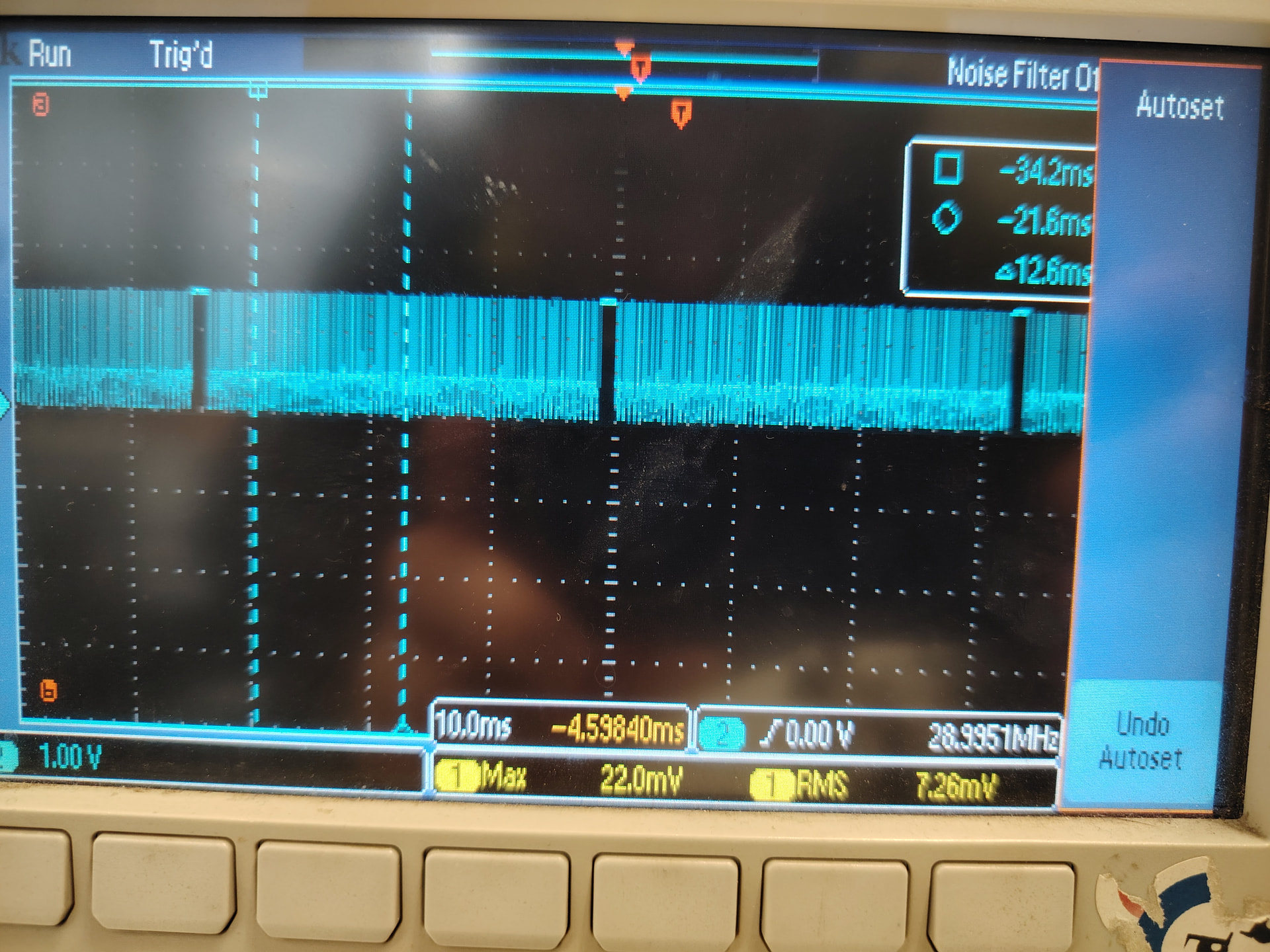
had you validate this sc1336 camera sensor before? please check it’s actually send MIPI signaling (high-speed signal), you may arrange hardware resources to probe the MIPI signaling on the CSI channel for confirmation.
FYI,
port-index = <0>; it maps to CSI-A; whereas port-index = <2>; it maps to CSI-C.
这个sc1336我们之前在其他设备上面使用过
port-index = <0>;映射到csi-0
port-index = <1>;映射到csi-1是这样吗?
我现在就是在csi0和csi1分别是rgb和ir,2lane,那么对应的port-index 应该分别是
rgb :
csi0
port-index = <0>;
tegra_sinterface = “serial_b”;
ir :
csi1
port-index = <1>;
tegra_sinterface = “serial_b”;
这样理解对吗
hello zhouleicheng,
tegra_sinterface should be identical with your port-index.
hence, you should have..
csi-0 / port-index = <0>; / tegra_sinterface = “serial_a”;
csi-1 / port-index = <1>; / tegra_sinterface = “serial_b”;
hi jerryChang,
我理解了,现在看起来我的设备树配置的是正确的
tegra234-camera-sc1336-dual.dtsi5.log (6.8 KB)
但是现在不知道为什么csi会显示超时
as mentioned, please check it’s actually send MIPI signaling (high-speed signal), you may arrange hardware resources to probe the MIPI signaling on the CSI channel for confirmation.
在上面论坛中我给出了rgb_rx0_dn0的示波器图像
看起来mipi是有输入的