I think the way you are thinking of this problem is wrong…
It is your hardware design… your hardware engineer should have some background knowledge about usb and he/she should provide initial idea to you first.
We need otg support so that device mode could be enabled… that is all we need. Whether what kind of port design to use, you should check with your hw engineer.
I understand.As our hardware guy was bit new to the internal details of USB, even though he has designed, I was trying study as much possible and start off before discussing with him for more details.
Mean while, we are not able to see nvidia corp. listing when we type “lsusb” now.
Our hardware guy says he has done same. wiring connections as yesterday where we could see “nvidia corporation…” for lsusb command.
We wanted this recovery mode (nvidia corporation listing with lsusb comand)so that we can try initrd flashing command and try to get the flash serial log. We are not able to proceed.
Any idea how to go about this?
Shall I try initird flashing command even without nvidia corp.and see If flashing proceeds? I will try it tmrw.
As the default BSP linux package from NVidia website will be loaded and flshed on the orion NX developer kit SOM module, which also supports recovery mode and flashing, I expected some device tree changes/updates already in this file, but I cannot see any device tree changes in this .dtsi file for configuring usb2-port 0 for OTG mode.
1)Could you explain this discrepancy?
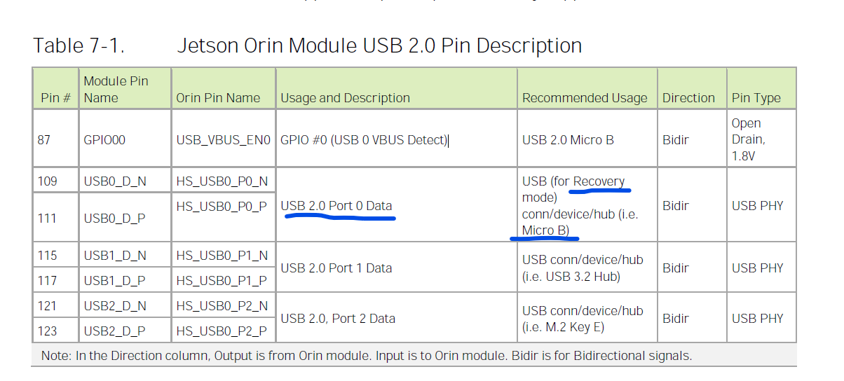
Also in the below snippet from product design guide, it recommends we should configure it as Micro B type of USB.
But our hardware guy says Type A also fine. please confirm which is the correct one.
“Recovery mode” is totally a hardware triggered event. You put some jumper to make the board in recovery mode, it triggered some pin inside and make it to be a usb device mode “through hardware”. This process is for the first “bootloader flash” as my explanation. After bootloader flash is done, this recovery mode is gone.
But the “usb device mode” needed for initrd flash needs to be done by using software. That is why device tree configuration is needed.
which also supports recovery mode and flashing, I expected some device tree changes/updates already in this file
What file are you talking about? Our device tree supports OTG too but in a type C way. It has such code. Orin Nano/NX devkit supports OTG mode… if you don’t believe me, you could test devkit on your side too.
Also in the below snippet from product design guide, it recommends we should configure it as Micro B type of USB.
But our hardware guy says Type A also fine. please confirm which is the correct one.
No, that is not correct. Have you ever seen there is someone use “type A” usb port to run as a usb device in your life? I guess not. All of them are all usb host mode…
Type A does not support OTG by its nature. Lacking of vbus_det pin and id pin.
Sorry, I trust you. We dont have development kit here to test. So the final conclusion is USB2.0 port 0 of Type C is used for flashing in recovery mode. First half of the flash is using hardware type recovery mode, second type using device tree update software method.
So we can customize device tree for Type B as well as per product guide?
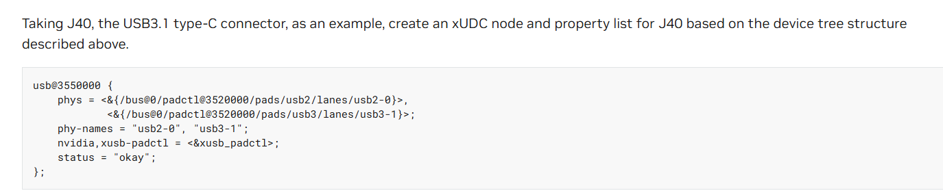
Does this looks fine.
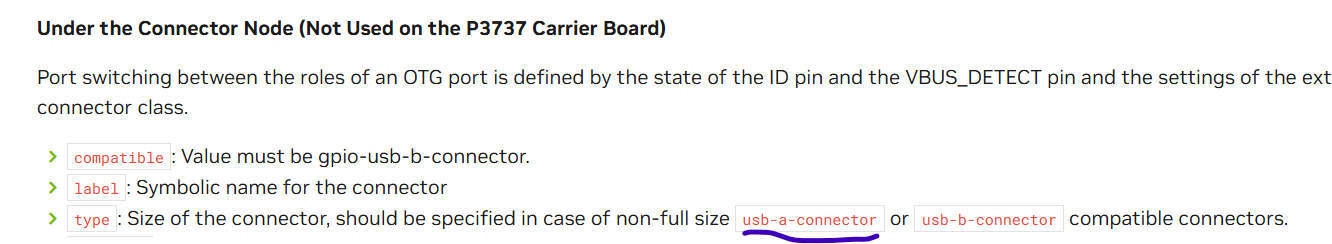
But I did not observe the connector node above for usb-c type.
Instead I see the below ctype node in the documentation link. Can you explain this variation with respect to type B and Type C customization while updating device tree…
I have read 2 times already. What ever questions I am asking is after reading there only. But some things are not clear. Only those things I am asking here for clarity.
but does not clearly tell whether
1)It is applicable for customized board for orion NX
2) If it not required or applicable for device tree, then why they have documented here.
As I already told, this whole document is applicable for any kind of Orin platforms… It is talking about general rules for usb device tree…
You misunderstood it… This document note is talking about “this section is not part of device tree of Orin AGX devkit because Orin AGX devkit does not use this solution.” Orin AGX devkit is using Cypress Type C controller as solution…
If you want to make a micro USB port on your board, then you need to refer to this section …
I see a mentioning of usb-a-connector here, I understand it is talking about type.
for usb-b-connector the type=“micro”.
in case of usb-a-connector as mentioned above what should be the type value?
You had told usb-a-connector wont be applicable here earlier. Its mentioned here as just a type. please clarify.
but they have used customize carrier board for there design, then this line AGX Orion Developer Kit should not appear in the dmesg log. Any justification for this?
I am not sure why you always focus on so many unrelated things…
This is just a string. If this user didn’t change it for their custom board, then it will be the original one as the devkit… because no one really write a device tree from scratch… they use NV device tree as template.
You are using a custom board on your side too. But if you didn’t change the string, its name will be same as devkit too…
I won’t be able to guide you like from the beginning how a device tree works here as this is Linux kernel things… you better reading some other online resources on the Internet first…
Sorry. I was trying to understand it much better. As things are very complex in NvIdia here and might many things are related in one way or the other.
Coming to device tree, I have basic idea of device tree and it usage. Already I have completed on project based on Jetson AGX Xavier Industrial where I customized audio codec sgtl5000 and brought up the audio sound functionality successfully.
Now, I have almost understood how to update device tree for our customized board for flashing port USB2.0 - port 0 which can be either micro USB or Type C. Thanks.
once our hardware guy fixes the recovery mode issue using hardware connection, I will try my flashing script with the updated device tree(DTB) for micro USB or type C( which ever hardware guy finalizes). Thanks.
It won’t work straight away. If it already worked in the beginning, you wouldn’t have filed this topic and asked…
You should study and figure out each meaning in the usb device tree and dig into each node.
For example, that fusb_p0 definitely not work on your side/custom board.