Hi @ffofocus, welcome!
For the first question, I’m not sure I understand. What does 1D mean in this context? Are you asking whether you can cast multiple rays that all have the same ray origin and ray direction, as if simulating a laser?
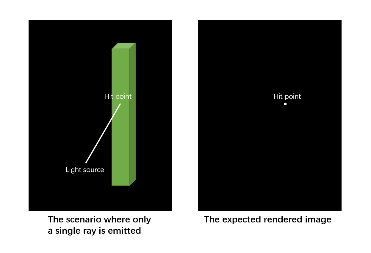
There’s nothing wrong with starting many ray paths using the exact same initial ray, but that does bring up a couple of things to think about. First, casting the same ray repeatedly will yield the same intersection point repeatedly. So an alternative, to avoid recomputing the same initial hit point over and over, is to first cast a single ray to find where the laser hits a surface, and only then cast multiple scattered rays from there that bounce around the scene. Second, you’ll need random scattering to ensure your rays don’t all go the same direction after the first bounce. To be more physically accurate, you also might want to perturb the initial ray’s position randomly by a small amount. I’ll stop here though, since if I misinterpreted your question, I’m just rambling.
I’m also not sure about the if statements part, what does it mean you can only use if statements? With OptiX specifically, and GPUs in general, the main problem with if statements occurs when the condition is different from thread to thread within a warp or wave. This causes the problem known as ‘execution divergence’, which reduces performance since threads that make conditional choices often have to stall and wait for neighboring threads that make different choices. It’s recommended to try to organize your code and data to ensure all threads execute the exact same code within a warp whenever possible. There are clever options that can help in some cases, but sometimes this is tricky or impossible (neighboring threads often hit different objects for example), so take this only as a vague high level goal, and don’t worry too much if you don’t see a solution. OptiX does offer a tool to help here, called Shader Execution Reordering.
For the second question, first keep in mind that OptiX has no notion of a camera or an observer. Those concepts are up to the application to provide. OptiX lets you test visibility along lines, and control what happens when rays hit or miss objects in your scene, but you get to put multiple lines (rays) together and decide where they start and end, and what the endpoints mean. While it’s extremely common in rendering to define a linear perspective camera somewhere with an “eye” point at the center of projection, there’s nothing stopping anyone from defining their ‘camera’ very differently, and indeed some people do. You have complete control over what shape and where the emitters and collectors are, and how you connect them using rays.
Some of our SDK samples are using this perspective camera convention, and they will trace ray paths starting at the eye/camera, and let them bounce around in the scene, tracing rays toward the light sources at each bounce to look for light or shadow. Just note that this eye+camera setup belongs to the SDK sample, not to the core OptiX library. You can very easily trace rays from your emitter (lights) toward the collector (camera), or trace rays from an emitter into the scene and see which ones hit the collector, or trace rays outward from both the emitters and collectors and link the paths up in the middle (aka “bidirectional path tracing”). The way to use a different ray origin position from the eye point is to write code in your raygen program that decides where each ray starts, and (if you want, for example) place it on an emitter rather than on the eye/camera image plane. Some applications like to do texture “baking” where they launch rays from the surface of objects in the scene, and collect the results into texture maps.
I hope I understood your questions correctly, but feel free to correct me or elaborate if I’m not giving you any helpful info yet.
–
David.