Finally I created a mesh out of particles using Marching Cubes and Mesh Smoothing (Laplacian).
Unfortunately some “black artefacts” occur.
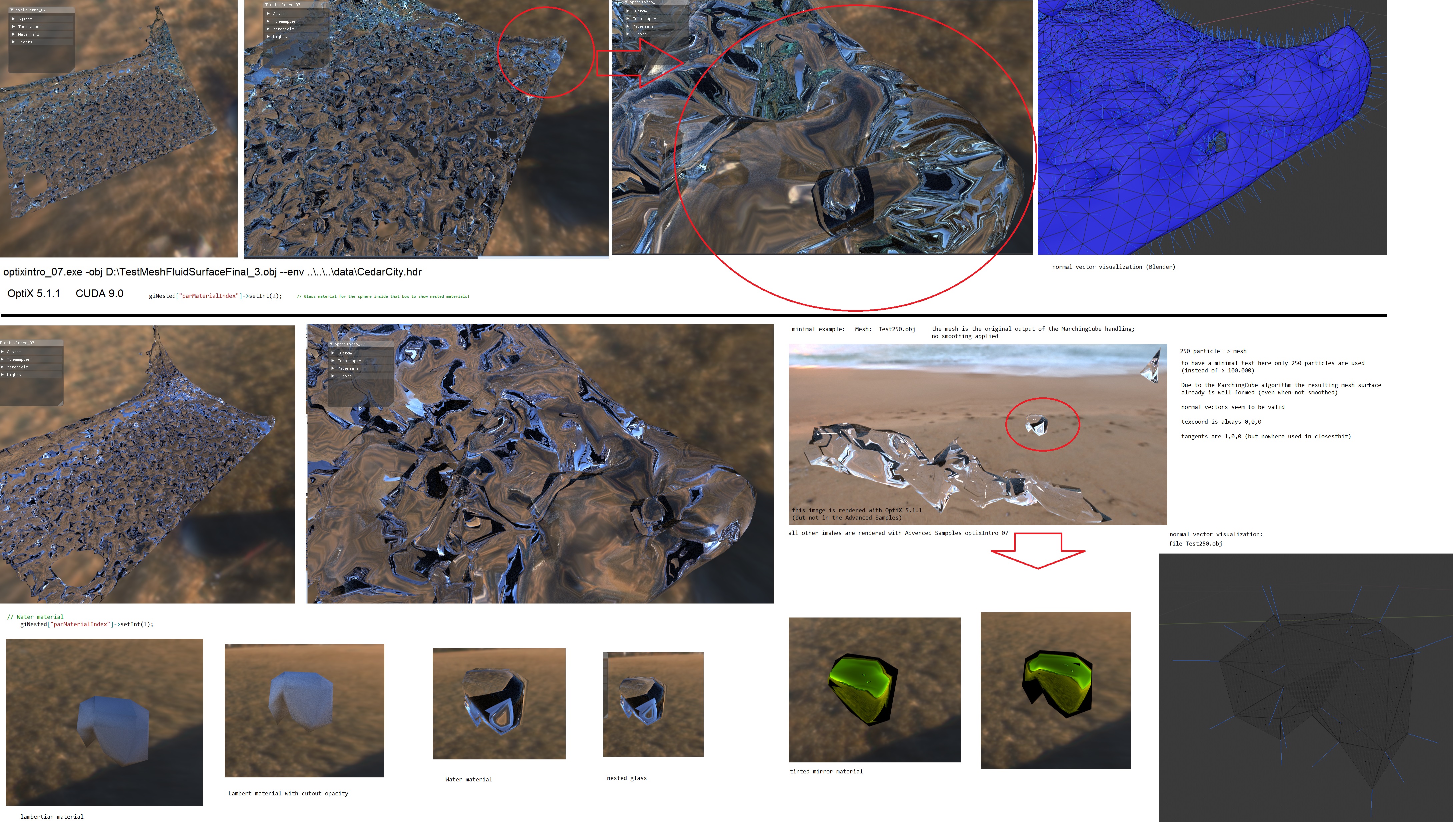
For a reproducing test I built Advanced Sample “optixIntro_07” from original files using the materials as defined there.
And then I only initialize “geoNested” with my mesh (no other geometry).
As you see in the screenshot, the normals seem to be ok. Tangents are not used in the closesthit program, so I don’t provide any.
TexCoords are all initialized to 0,0,0
the mesh is in .OBJ format (RH CCW) which is the same as mesh handling in the samples are using. File: Test250.obj
(I added a simply .OBJ loader)
For a very small piece of the mesh I rendered it with different materials from optixIntro_07 sample.
On Water, Glass and Tinted mirror material the artefacts occur; they do not occur, when rendered with lambertian material.
These black parts also appear when using the default environment map in the sample.
No denoiser used.
the mesh is very simple organized (each vertex has exactly one vertex normal and they are used always coupled):
v x y z
vn x y z
…
f i//i –
What could still be wrong with the mesh?
Thank you.
my system: OptiX 5.1.1 CUDA 9.0 Win10PRO driver 398.36 GTX 1050 2GB VS2017 (toolset v140 of VS2015)
(the particles were generated through NVIDIA Flex) Test250.zip (10.4 KB)
The mesh resolution is much too small for the per vertex smooth normals. Sampling such a low resolution surface with smooth shading normals will shoot continuation rays below the geometric surface and that is a path-ending condition in these examples.
While this is a general problem, the transparent material is going to show additional dark artifacts when the path length is not long enough.
Simply increase the maximum path length in the GUI from the default to something higher, like 10 or more.
You should also try to switch off the Russian Roulette path termination by setting a minimum path length greater or equal to the maximum path length for the full effect of the the path length in transparent materials.
Thank you very much!
Obviously I’m too stupid to read… :)
For the specular reflection I simply apply the (standard practice) flipping-normals-trick from the paper you mentioned. That works great.
On the transmission case I simply increased the Max Path to 20 and applied subdivision surface on the mesh. Now its working great!
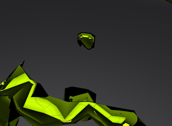
You cannot simply flip the normals on a specular reflection. That’s going to reflect the continuation ray into an incorrect direction and will introduce discontinuities in the shading.
Compare the border of the green object to the case when doing the reflection with the geometric normal instead.
Why are the transparent objects looking facetted now?
They should have become smoother if you increased the tessellation and still used smoothed per vertex normals for shading, or did you let Blender generate geometric normals per triangle?
That would be slower because that prevents vertex reuse in the triangle mesh topology due to unique normals on adjacent triangles.
So basically the only option seems to be to increase the mesh resolution.
Yes, the “facetted” mesh uses face-normals, cause in that case even without subdivision the result has much lesser black artefacts. And unfortunately obviously only subdivision level >= 3 removes the artefacts completely; I also played around with Min+Max Path, but a higher resolution seems to improve quality much better.
I also removed the flipped normals; Works fine now with 3x subdivision.
All they run without problems in the test sample, but the final fluid has >190.000 particles
=> mesh then has about 28000 vertices (when using shared vertex normals) and 57720 faces