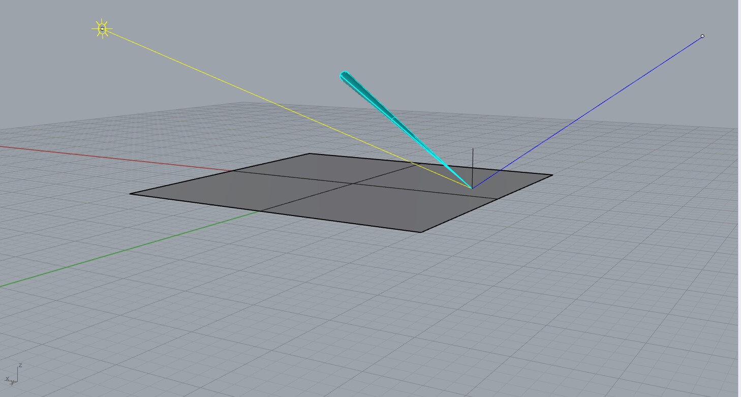
To your screenshots:
First of all that small light shape looks like a triangle, not like a parallelogram.
Then the lighting effect on your surface is not at all where it should be if that parallelogram light is the only light in your scene.
Looking into the optixBoundValues example, that is implementing a very simple path tracer with a Lambert surface material (seen by the cosine_sample_hemisphere() function in the device code) and a single parallelogram light source using direct lighting and four different material colors and emissions.
If you look through the C++ sources, you’ll see that the light is represented in one part by the parallelogram data structure which is used for explicit light sampling only.
This is the definition of the parallelogram light inside the host code:
    state.params.light.emission = make_float3( 15.0f, 15.0f, 5.0f );
    state.params.light.corner   = make_float3( 343.0f, 548.5f, 227.0f );
    state.params.light.v1       = make_float3( 0.0f, 0.0f, 105.0f );
    state.params.light.v2       = make_float3( -130.0f, 0.0f, 0.0f );
    state.params.light.normal   = normalize( cross( state.params.light.v1, state.params.light.v2 ) );
and this is the code doing the explicit light sampling for the direct lighting:
        ParallelogramLight light = params.light;
        const float3 light_pos = light.corner + light.v1 * z1 + light.v2 * z2;

        // Calculate properties of light sample (for area based pdf)
        const float  Ldist = length( light_pos - P );
        const float3 L     = normalize( light_pos - P );
        const float  nDl   = dot( N, L );
        const float  LnDl  = -dot( light.normal, L );
Now that is not all. To be able to hit the light geometry implicitly (when the ray randomly goes into the direction of the light after sampling the continuation ray of the BRDF), it is also defined as two hardcoded triangles inside the geometry data here:
    // Ceiling light -- emissive
    {  343.0f,  548.6f,  227.0f, 0.0f },
    {  213.0f,  548.6f,  227.0f, 0.0f },
    {  213.0f,  548.6f,  332.0f, 0.0f },

    {  343.0f,  548.6f,  227.0f, 0.0f },
    {  213.0f,  548.6f,  332.0f, 0.0f },
    {  343.0f,  548.6f,  332.0f, 0.0f }
You’ll see that these hardcoded coordinates match exactly.
Both these places must be changed to have the explicit light sampling and the implicit light geometry hits work together correctly! I would guess you had only changed one of the two.
Mind that when changing geometry positions inside the scene, the geometry acceleration structure must be updated or rebuilt! You cannot simply change the parametric representation of the light alone if it’s represented with geometry inside the scene.
https://raytracing-docs.nvidia.com/optix7/guide/index.html#acceleration_structures#dynamic-updates
I wouldn’t have hardcoded the geometry triangle but would have calculated the resulting triangles from the parallelogram parameters. Shown in this more advanced example: https://github.com/NVIDIA/OptiX_Apps/blob/master/apps/nvlink_shared/src/Application.cpp#L540
Note that the implicit light hits will return the colors and emission values from the material index 3:
static std::array<uint32_t, TRIANGLE_COUNT> g_mat_indices = {{
    0, 0,                          // Floor         -- white lambert
    0, 0,                          // Ceiling       -- white lambert
    0, 0,                          // Back wall     -- white lambert
    1, 1,                          // Right wall    -- green lambert
    2, 2,                          // Left wall     -- red lambert
    0, 0, 0, 0, 0, 0, 0, 0, 0, 0,  // Short block   -- white lambert
    0, 0, 0, 0, 0, 0, 0, 0, 0, 0,  // Tall block    -- white lambert
    3, 3                           // Ceiling light -- emissive
}};
and the emission of that is not white but RGB (15, 15, 5):
const std::array<float3, MAT_COUNT> g_emission_colors =
{ {
    {  0.0f,  0.0f,  0.0f },
    {  0.0f,  0.0f,  0.0f },
    {  0.0f,  0.0f,  0.0f },
    { 15.0f, 15.0f,  5.0f }
} };
and weirdly enough, the surface color of the light geometry (the last entry again) is not black. (I would change that as well.)
const std::array<float3, MAT_COUNT> g_diffuse_colors =
{ {
    { 0.80f, 0.80f, 0.80f },
    { 0.05f, 0.80f, 0.05f },
    { 0.80f, 0.05f, 0.05f },
    { 0.50f, 0.00f, 0.00f }
} };
Now with all that explained, if you want to simulate lighting by the sun there are better ways to implement that.
I wouldn’t use a geometric primitive to represent the sun simply because you wouldn’t actually place that with the actual physical size and distance into the scene but would need to scale and place it nearer to not run out of floating precision bits of your scene units.
Instead the sun is usually implemented as a directional light with a normalized direction vector from surface point to the light and a proper cone spread angle to simulate the solid angle of 0.53 for the sun “disk” when seen from earth.
Means explicit light sampling would need to sample directions inside that cone only.
Changing that direction vector would then directly represent the elevation and direction of the sun relative the earth surface point.
There would not need to be geometry inside the scene for the sun, which means implicit light hits of the sun would be implemented inside the miss program by checking if the angle between ray direction and sun direction is smaller than the cone spread angle (that’s a dot product and a comparison).
That effectively places the sun infinitely far away. Because there wouldn’t be any geometry representing the sun, there also wouldn’t need to be any rebuild of the acceleration structures required! You could simply change the sun direction inside your OptiX launch parameters and restart the rendering.
The sun would always result in a perfectly circular shape when seen directly (except for projection distortions of the camera implementation).
The effect on the surface, means the change from more circular lighting effects (when the sun and view directions are perpendicular to the surface, i.e. when surface normal and light direction and view direction are the same) to more spread out elliptical shapes is a matter of the bi-directional reflection distribution function (BRDF) and the angles between normal and view direction (to the observer) and normal and light direction (to the sun). This gets much more pronounced when using glossy reflections instead of purely diffuse materials.
In addition to the simple sun disk light there would be much more elaborate sun and sky models which simulate the atmospheric scattering as well if you’d want to implement a more physically correct sun and sky lighting. Search for articles about Mie and Rayleigh scattering.