Transpose example, strange dim dependent lagg..

Hi!

I’ve written a transpose example that i believe is identical to the one in the CUDA SDK.

I get higher and higher speedups for larger data sets (150x + ) but after doing some tampering i noticed that only certain dimensions of the matrix gave a high speed up.

If i have a matrix A with DIM = n by m i might get a speedup of 150x, later if i switch the dimensions and make A m by n the speedup drops to maybe 50x.

I’ve checked my code and i’m avoiding both bank conflicts (see oddly dimmed shared block) and also doing coalesced reads and writes.

And yes my grid is dimensioned after the data and block dimensions.

As:

dim3 dimBlock(block_x, block_y);

dim3 dimGrid( (block_x + n -1) / block_x, (block_y+m-1)/block_y);

See my kernel code below:

[codebox]global static void corner_turn_smart(float* A, float* B, int n, int m)

{

// Put a block in shared memory

// We add an extra column because we are smart :)

__shared__ float block[block_x][block_y + 1];

// Matrix indices

unsigned int i = threadIdx.y + blockDim.y*blockIdx.y;

unsigned int j = threadIdx.x + blockDim.x*blockIdx.x;

if( i < n && j < m)  // make sure we are within limits

{

	// read from A into shared, perform corner turn

	block[threadIdx.y][threadIdx.x] = A[j + i*m];


}

// Makes sure all the threads are finished

__syncthreads();


// read from the shared memory block into the result matrix


// Remember that we are not working on the transposed matris, the indices need to be

// redefined

i = threadIdx.y + blockDim.x*blockIdx.x;

j = threadIdx.x + blockDim.y*blockIdx.y;


if( i < m && j < n)

{

	// Every block is here written back into the result matrix.

	// 

	B[j + i*n] = block[threadIdx.x][threadIdx.y]; 

}

}[/codebox]

I tried the transpose in the SDK. It suffered from the same issues. Is there somewhere were i am still doing non-coalesced reads or writes ? I’ve also tested the fact that the shared block avoids banking conflicts.

I’m really curious to figure out what is going wrong here. My kernel currently enjoys when it gets n << m (not a bit shift ! :) ) but not when n >> m.

What limitation am i hitting here?

Cheers!

Jimmy

  1. there is something wrong with your code

try n = 32 and m = 33 and configure matrix A as

[codebox] for( i = 0; i < (m * n); ++i)

{

    A[i] = i; 

}[/codebox]

then A(0,32) = 32 != B(32,0)

  1. when n = m and block_x = block_y, then your method is indeed optimized method in SDK

and your code has the same performance as optimized method.

I guess that your excess speedup comes from wrong result, maybe you don’t move all data such that

you have wrong speedup

Hi LSChien,

I’m checking that the results are correct against a CPU implementation, so I’m sure the results are correct.

In my method block_x=block_y allways.

The method I’m refering to (transpose in SDK) doesn’t require n=m, also computes the right result, and also suffers from the same issue.

So to conclude, the results are correct, but the real question is why there are speedup differences?

Wo you shenme wenti?

//jp

Did you look at the transposeNew sample of the CUDA 2.3 SDK, and the associated whitepaper? I think it may answer your question. ;)

hey,

yeah i’ve been skimming through the white paper. I’m a little sleepy now but a flimsy guess could be that it is related to the mentioned partition camping…

Will read up on it later :)

//j

thanks to Sylvain Collange, I read document in SDK/transposeNew and re-experiment tranpose operation

I focus on coalesced transpose (optimized method in SDK/transpose) and plot bandwidth over dimension n1, n2

I do experiment on Tesla C1060 and use data type = “double”

experiment 1: set n1 = n2, then graph is shown in figure 1

figure 1

one can see two curves with low bandwidth in figure 1, one is near 20 GB/s, the other is near 30 GB/s.

if we extract dimension N which has bandwdith less than 25GB/s and slowest curve is shown in figure 2

figure 2

moreover N is multiple of 256. This can be interpreted by document in SDK/transposeNew.

"global memory is divided into either 6 partitions (on 8- and 9-series GPUs) or 8 partitions (on 200-

and 10-series GPUs) of 256-byte width."

Tesla C1060 has 8 partitions of 256-byte, all data in strides of 2048 bytes (256 double) map to the same partition.

Hence in our experiment (type = “double”), when N = multiple of 256, then active blocks almost fall into the same

partition such that throughput of “write operation” decreases.

That is why “diagonal block reordering” appears in SDK/transposeNew

experiment 2: sweep n1 != n2 and I want to show asymmetry of performance observed by Jimmy Pettersson.

In figure 3, we plot bandwdith over (n1,n2), n1, n2 = 200:800. one can see some low bandwidth sample near

n1 = 500 or 800

figure 3

if we extract dimension (n1,n2) which has bandwidth less than 30GB/s, then result is shown in figure 4

figure 4

clearly, from figure 4 speedup is asymmetric.

experiment 3: I compare “coalesced transpose” and “tranpose with diagonal reordering”

platform: Tesla C1060, data type = “double”

method 1: coalesced transpose

method 2: tranpose with diagonal reordering

[codebox]-----------±----------------------±----------------------+

n1,n2 | GPU method 1 | GPU method 2 |

       | (time, bandwidth)     | (time, bandwidth)     |  

-----------±----------------------±----------------------+

32, 32 | 0.007 ms, 2.13 GB/s | 0.009 ms, 1.79 GB/s |

-----------±----------------------±----------------------+

64,64 | 0.007 ms, 8.52 GB/s | 0.009 ms, 7.09 GB/s |

-----------±----------------------±----------------------+

128,128 | 0.009 ms, 26.49 GB/s | 0.011 ms, 22.76 GB/s |

-----------±----------------------±----------------------+

256,256 | 0.034 ms, 28.05 GB/s | 0.024 ms, 40.48 GB/s |

-----------±----------------------±----------------------+

512,512 | 0.151 ms, 25.26 GB/s | 0.067 ms, 58.62 GB/s |

-----------±----------------------±----------------------+

1024,1024 | 0.756 ms, 20.18 GB/s | 0.241 ms, 64.73 GB/s |

-----------±----------------------±----------------------+

2048,2048 | 3.434 ms, 17.77 GB/s | 0.941 ms, 66.41 GB/s |

-----------±----------------------±----------------------+

4096,4096 | 14.863 ms, 16.43 GB/s | 3.709 ms, 67.41 GB/s |

-----------±----------------------±----------------------+

8192,8192 | 67.662 ms, 14.43 GB/s | 14.543 ms, 68.76 GB/s |

-----------±----------------------±----------------------+ [/codebox]

conclusion: for n1 = n2 = multiple of 256, we need to use diagonal reordering technique,

otherwise coalesced method is good enough for n1 = n2.

as for asymmetric property of coalesed method, I have no idea so far.

I have an explanation of asymmetric of bandwidth result.

look at figure 4

the experiment acts on a 2-D data set with dimension N1 x N2, say A(1:N1, 1:N2)

[codebox]

 <--- N2 --->                                      <--- N1 ---> 

 +----------+                                      +----------+

^ | | ^ | |

| | A | , transpose to B(1:N2, 1:N1) | | B |

N1 | | N2 | |

| | | | | |

v ±---------+ v ±---------+

[/codebox]

values of N1 and N2 do not affect coalesced property of “read operation” in coalesced method,

active warps are divided evenly among partitions. However value of N1 is important for “write operation”,

when N1 is multiple of 256 “double” ( 2048 bytes, i.e. 8 partitions of 256-byte width), then active blocks

in Cartesian coordinate would fall into the same partition, then throughput decreases.

This shows asymmetry of bandwidth over (N1, N2) since only value of N1 can affect “partition camping”.

( partition camping is used to describe the case when global memory accesses are directed

through a subset of partitions, causing requests to queue up at some partitions

while other partitions go unused )

From figure 4, N1 = 256, 512, 768 have poor bandwidth, this proves above explanation.

Second I do the same experiment on GTX295, set N1 = N2, then graph is shown in figure 5.

At first glance, figure 5 is the same as figure 1, however if we resolve slowest curve (figure 6), then

you can see something different.

figure 5

In figure 6, N is multiple of 32, but with stride = 7. This means that global memory of GTX295 has 7 partitions

of 256-byte (32 “double”).

figure 6

assertion: Given data A(1:N1, 1:N2) of type “double”,

I want to show that diagonal ordering only has benefit when N1 is multiple of 256 on Tesla C1060.

from above disccusion, Tesla C1060 has 8 partitins of 256-byte width (or say 32-double width), so all

data in strides of 8 x 32 = 256 doubles map to the same partition. That is why we have dramatic

performance degradation when N1 is multiple of 256.

first I want to verify performance of diagonal ordering for arbitrary dimension.

I modify original code (called method 1) such that boundary condition is considered,

I call modified code as method 2

method 1: orignal diagonal-ordering method, only valid for N = multiple of 32

[codebox]define TILE_DIM 32

define BLOCK_ROWS 8

int xIndex = blockIdx_x * TILE_DIM + threadIdx.x;

int yIndex = blockIdx_y * TILE_DIM + threadIdx.y;

int index_in = xIndex + (yIndex)*width;

xIndex = blockIdx_y * TILE_DIM + threadIdx.x;

yIndex = blockIdx_x * TILE_DIM + threadIdx.y;

int index_out = xIndex + (yIndex)*height;

for (int i=0; i<TILE_DIM; i+=BLOCK_ROWS) {

tile[threadIdx.y+i][threadIdx.x] = idata[index_in+i*width];

}

__syncthreads();

for (int i=0; i<TILE_DIM; i+=BLOCK_ROWS) {

  odata[index_out+i*height] = tile[threadIdx.x][threadIdx.y+i];

}[/codebox]

method 2: modified diagonal-ordering method, valid for arbitrary N

[codebox] int xIndex = blockIdx_x * TILE_DIM + threadIdx.x;

int yIndex = blockIdx_y * TILE_DIM + threadIdx.y;

int index_in = xIndex + (yIndex)*width;

for (int i=0; i<TILE_DIM; i+=BLOCK_ROWS) {

if( (xIndex < width) && ( (yIndex+i) < height) ){  

	tile[threadIdx.y+i][threadIdx.x] = idata[index_in+i*width];

}

}

__syncthreads();

xIndex = blockIdx_y * TILE_DIM + threadIdx.x;

yIndex = blockIdx_x * TILE_DIM + threadIdx.y;

int index_out = xIndex + (yIndex)*height;

for (int i=0; i<TILE_DIM; i+=BLOCK_ROWS) {

if( (xIndex < height) && ( (yIndex+i) < width)){  

  odata[index_out+i*height] = tile[threadIdx.x][threadIdx.y+i];

}

}[/codebox]

experimental result on Tesla C1060, data type = double

[codebox]-----------±----------------------±----------------------+

n1,n2 | GPU method 1 | GPU method 2 |

       | (time, bandwidth)     | (time, bandwidth)     |  

-----------±----------------------±----------------------+

32, 32 | 0.009 ms, 1.79 GB/s | 0.012 ms, 1.22 GB/s |

-----------±----------------------±----------------------+

64,64 | 0.009 ms, 7.09 GB/s | 0.012 ms, 4.93 GB/s |

-----------±----------------------±----------------------+

128,128 | 0.011 ms, 22.76 GB/s | 0.013 ms, 19.32 GB/s |

-----------±----------------------±----------------------+

256,256 | 0.024 ms, 40.48 GB/s | 0.030 ms, 32.98 GB/s |

-----------±----------------------±----------------------+

512,512 | 0.067 ms, 58.62 GB/s | 0.079 ms, 49.31 GB/s |

-----------±----------------------±----------------------+

1024,1024 | 0.241 ms, 64.73 GB/s | 0.289 ms, 54.10 GB/s |

-----------±----------------------±----------------------+

2048,2048 | 0.941 ms, 66.41 GB/s | 1.122 ms, 55.72 GB/s |

-----------±----------------------±----------------------+

4096,4096 | 3.709 ms, 67.41 GB/s | 4.475 ms, 55.87 GB/s |

-----------±----------------------±----------------------+

8192,8192 | 14.543 ms, 68.76 GB/s | 17.963 ms, 55.67 GB/s |

-----------±----------------------±----------------------+ [/codebox]

modified code need extra comparisons in boundary condtion, so it is slower than original code.

second, sweep n1 = n2, and show bandwidth in figure 7. If we compare figure 7 with figure 1

which is result of “coalesced transpose”, then they have two slow curves in common.

But averagely speaking (exclude two slow curves), “coalesced transpose” is better than “diagonal transpose”.

figure 7

We extract slowest curve (dimension N which has bandwdith less than 25GB/s) in figure 7 and show it in figure 8.

Then N+1 is multiple of 256, this is different from result of figure 2 (N is multiple of 256)

figure 8

Question: why does performance degradation of “diagonal ordering” occur at N+1 = multiple of 256?

Ans: We use Tesla C1060 which has 8 partitions of 256-byte width (or say 32 doubles width),

so all data in strides of 8 x 32 = 256 doubles map into the same partition.

In order to simplify discussion, let us assume 4 partitions of 2-double width,

then all data in strides of 4 x 2 = 8 doubles map into the same partition.

Here we choose N = N1 = N2 = 7 and TILE_DIM = 2.

we use 4 colors to represent 4 partitions, first partition is red, second is blue, third is orange and fourth is green.

data set A(1:7, 1:7) can be arranged as square matrix and we color each data element to show its partition,

the whole matrix is shown in left panel of figure 9.

right panel of figure 9 is placement of blocks in Cartesian coordinate when do “read operation”, note that

each block has dimension 2x2 since TILE_DIM=2 is assumed.

figure 9

block 0~3 access 4 partitions and achieve high bandwidth,

similarly, block 4~7, block 8~11, and block 12~15 all access 4 partitions.

The same thing holds in Cartesian coordinate whne do “wrtie operation”, see figure 10.

block 0~3, block 4~7, block 8~11, and block 12~15 all access 4 partitions.

figure 10

However when we talk about diagonal-ordering, things are totally different.

In figure 11, we shown placement of blocks in Diagonal coordinate when do “read operation”.

block 0~3 only access 2 partitions (red color and Green color), so it has low bandwidth.

similarly, block 4~7, block 8~11, and block 12~15 all access 2 partitions.

figure 11

Situation does not change even in “write operation”, see figure 12

figure 12

above discussion demonstrate why N+1=multiple of 256 has slowest performance.

finally I want to show symmetric property of diagonal-ordering.

sweep n1 != n2, and show bandwidth in figure 13. Roughly speaking, the graph is symmetric.

if we extract dimension pari (N1,N2) which has bandwidth less than 30GB/s, and show result

in fugre 14, then it is symmetric if one focus on N1 > 500 and N2 > 500

figure 13

figure 14

Question: why does diagonal-ordering keep symmetric property whereas coalesced method does not?

Ans: Suppose A has dimension 511 x 60, then “write operation” has slow performance due to

partition camping when do diagonal-ordering. How about transpose of A, with dimension 60 x 511?

now transpose of A has slow performance in “read operation” due to partition camping when do

diagonal-ordering.

Impressive work on PC subject! I found the white paper to be quite interesting!

I modify diagonal-ordering to adapt to arbitrary dimension last post and have conclusion

“modified code need extra comparisons in boundary condtion, so it is slower than original code.”

Now I need to correct this statement since I found the way to speedup diagonal-ordering of general form.

the ideas have two parts:

part 1: fixedpoint modulo operation

The original code (below) in SDK/transposeNew use operator % to do modulo operation, this is slow.

[codebox] // do diagonal reordering

if (width == height) {

blockIdx_y = blockIdx.x;

blockIdx_x = (blockIdx.x+blockIdx.y)%gridDim.x;

} else {

int bid = blockIdx.x + gridDim.x*blockIdx.y;

blockIdx_y = bid%gridDim.y;

blockIdx_x = ((bid/gridDim.y)+blockIdx_y)%gridDim.x;

} [/codebox]

I use technique discussing in thread http://forums.nvidia.com/index.php?showtopic=106232

(technique is provided by SPWorley and call it as “fixed-point multiply method” by Sylvain Collange.

later I will call this modulo operation as “fixedpoint method” )

one needs to compute one_over_gx = 2^32/gridDim.x and one_over_gy = 2^32/gridDim.y in host code, then

pass one_over_gx and one_over_gy into kernel function to use integer multiplication to do modulo operation.

The code segment in the kernel function is

[codebox] unsigned int tmp1, tmp2 ;

// do diagonal reordering

if (width == height) {

	blockIdx_y = blockIdx.x;

	tmp1 = blockIdx.x + blockIdx.y ;

	tmp2 = __umulhi( tmp1, one_over_gx ); 		

	blockIdx_x = tmp1 - gridDim_x * tmp2 ;

} else {

unsigned int bid = blockIdx.x + gridDim.x*blockIdx.y;

	blockIdx_x = __umulhi( bid, one_over_gy ); 				

	blockIdx_y = bid - blockIdx_x * gridDim_y ;

	bid = blockIdx_x + blockIdx_y ;

	tmp1 = __umulhi( bid, one_over_gx );

	blockIdx_x = bid - tmp1 * gridDim_x ; 	

} [/codebox]

and it C-wrapper computes one_over_gx and one_over_gy as

[codebox] dim3 threads(TILE_DIM,BLOCK_ROWS);

dim3 grid( (width+TILE_DIM-1)/TILE_DIM, (height+TILE_DIM-1)/TILE_DIM) ;

double max_int ;

max_int = 4.294967296000000e+009 ; // 2^(32) 


unsigned int one_over_gx = (unsigned int) ceil( max_int/((double)grid.x)) ; 

unsigned int one_over_gy = (unsigned int) ceil( max_int/((double)grid.y)) ;[/codebox]

part 2: loop unrolling

recall the code method 2 of last post,

method 2: modified diagonal-ordering method, valid for arbitrary N

[codebox] int xIndex = blockIdx_x * TILE_DIM + threadIdx.x;

int yIndex = blockIdx_y * TILE_DIM + threadIdx.y;

int index_in = xIndex + (yIndex)*width;

for (int i=0; i<TILE_DIM; i+=BLOCK_ROWS) {

if( (xIndex < width) && ( (yIndex+i) < height) ){  

	tile[threadIdx.y+i][threadIdx.x] = idata[index_in+i*width];

}

}

__syncthreads();

xIndex = blockIdx_y * TILE_DIM + threadIdx.x;

yIndex = blockIdx_x * TILE_DIM + threadIdx.y;

int index_out = xIndex + (yIndex)*height;

for (int i=0; i<TILE_DIM; i+=BLOCK_ROWS) {

if( (xIndex < height) && ( (yIndex+i) < width)){  

  odata[index_out+i*height] = tile[threadIdx.x][threadIdx.y+i];

}

}[/codebox]

My idea is

(1) move condition (xIndex < height) outside for-loop and then

(2) unroll the for-loop manually

for read-operation, the unrolling code is

[codebox] int xIndex = blockIdx_x * TILE_DIM + threadIdx.x;

int yIndex = blockIdx_y * TILE_DIM + threadIdx.y;

int index_in = xIndex + (yIndex)*width;

if( xIndex < width){

int B_mul_w = BLOCK_ROWS*width ;

if ( (yIndex+3*BLOCK_ROWS) < height ){

	tile[threadIdx.y               ][threadIdx.x] = idata[index_in            ];

	tile[threadIdx.y +   BLOCK_ROWS][threadIdx.x] = idata[index_in +   B_mul_w];

	tile[threadIdx.y + 2*BLOCK_ROWS][threadIdx.x] = idata[index_in + 2*B_mul_w];

	tile[threadIdx.y + 3*BLOCK_ROWS][threadIdx.x] = idata[index_in + 3*B_mul_w];	

}else if ( (yIndex+2*BLOCK_ROWS) < height ){

	tile[threadIdx.y               ][threadIdx.x] = idata[index_in            ];

	tile[threadIdx.y +   BLOCK_ROWS][threadIdx.x] = idata[index_in +   B_mul_w];

	tile[threadIdx.y + 2*BLOCK_ROWS][threadIdx.x] = idata[index_in + 2*B_mul_w];

}else if ( (yIndex+BLOCK_ROWS) < height ){ 

	tile[threadIdx.y               ][threadIdx.x] = idata[index_in            ];

	tile[threadIdx.y +   BLOCK_ROWS][threadIdx.x] = idata[index_in +   B_mul_w];

}else if ( yIndex < height ){

	tile[threadIdx.y][threadIdx.x] = idata[index_in];

}

}// if (xIndex < weight)

__syncthreads();[/codebox]

for write-operation, the unrolling code is

[codebox] xIndex = blockIdx_y * TILE_DIM + threadIdx.x;

yIndex = blockIdx_x * TILE_DIM + threadIdx.y;

int index_out = xIndex + (yIndex)*height;

if( xIndex < height){

int B_mul_h = BLOCK_ROWS*height ;

if ( (yIndex+3*BLOCK_ROWS) < width ){

	odata[index_out             ] = tile[threadIdx.x][threadIdx.y               ];

	odata[index_out +   B_mul_h ] = tile[threadIdx.x][threadIdx.y +   BLOCK_ROWS];

	odata[index_out + 2*B_mul_h ] = tile[threadIdx.x][threadIdx.y + 2*BLOCK_ROWS];

	odata[index_out + 3*B_mul_h ] = tile[threadIdx.x][threadIdx.y + 3*BLOCK_ROWS];

}else if ( (yIndex+2*BLOCK_ROWS) < width ){

	odata[index_out             ] = tile[threadIdx.x][threadIdx.y               ];

	odata[index_out +   B_mul_h ] = tile[threadIdx.x][threadIdx.y +   BLOCK_ROWS];

	odata[index_out + 2*B_mul_h ] = tile[threadIdx.x][threadIdx.y + 2*BLOCK_ROWS];

}else if ( (yIndex+ BLOCK_ROWS) < width ){

	odata[index_out             ] = tile[threadIdx.x][threadIdx.y               ];

	odata[index_out +   B_mul_h ] = tile[threadIdx.x][threadIdx.y +   BLOCK_ROWS];

}else if ( yIndex < width ){

	odata[index_out] = tile[threadIdx.x][threadIdx.y];

} 

}// if (xIndex < height)[/codebox]

now I call “diagonal-ordering + fixedpoint + loop-unrolling” as method 3.

Remark: one may wonder why not using “#pragma unroll” and let compiler to do optimization,

however experiment shows no benefit. (I don’t know why, maybe we need to check it PTX code,

so far I don’t want to go such deep further)

To sum up, we have three methods and do experiment on Tesla C1060 (data of method 1 and method 2

are the same as last post, we just calibrate method 3)

method 1: orignal diagonal-ordering method, only valid for N = multiple of 32

method 2: modified diagonal-ordering method, valid for arbitrary N

method 3: diagonal-ordering + fixedpoint + loop-unrolling

experimental result on Tesla C1060, data type = double

[codebox]-----------±----------------------±----------------------±----------------------+

n1,n2 | GPU method 1 | GPU method 2 | GPU method 3 |

       | (time, bandwidth)     | (time, bandwidth)     | (time, bandwidth)     |

-----------±----------------------±----------------------±----------------------+

32, 32 | 0.009 ms, 1.79 GB/s | 0.012 ms, 1.22 GB/s | 0.009 ms, 1.79 GB/s |

-----------±----------------------±----------------------±----------------------+

64,64 | 0.009 ms, 7.09 GB/s | 0.012 ms, 4.93 GB/s | 0.009 ms, 7.07 GB/s |

-----------±----------------------±----------------------±----------------------+

128,128 | 0.011 ms, 22.76 GB/s | 0.013 ms, 19.32 GB/s | 0.011 ms, 22.75 GB/s |

-----------±----------------------±----------------------±----------------------+

256,256 | 0.024 ms, 40.48 GB/s | 0.030 ms, 32.98 GB/s | 0.024 ms, 40.98 GB/s |

-----------±----------------------±----------------------±----------------------+

512,512 | 0.067 ms, 58.62 GB/s | 0.079 ms, 49.31 GB/s | 0.066 ms, 58.75 GB/s |

-----------±----------------------±----------------------±----------------------+

1024,1024 | 0.241 ms, 64.73 GB/s | 0.289 ms, 54.10 GB/s | 0.241 ms, 64.92 GB/s |

-----------±----------------------±----------------------±----------------------+

2048,2048 | 0.941 ms, 66.41 GB/s | 1.122 ms, 55.72 GB/s | 0.940 ms, 66.49 GB/s |

-----------±----------------------±----------------------±----------------------+

4096,4096 | 3.709 ms, 67.41 GB/s | 4.475 ms, 55.87 GB/s | 3.710 ms, 67.38 GB/s |

-----------±----------------------±----------------------±----------------------+

8192,8192 | 14.543 ms, 68.76 GB/s | 17.963 ms, 55.67 GB/s | 14.550 ms, 68.73 GB/s |

-----------±----------------------±----------------------±----------------------+ [/codebox]

now method 3 is almost the same as method 1 (remember method 1 only works for N = multiple of 32).

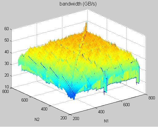
second, we answer question “why does performance degradation of “diagonal ordering” occur at N+1 = multiple of 256?”

last post. In fact, diagonal-ordering has two slow curves, one is (N+1) = multiple of 256, the other is

(N-128+1) is multiple of 256. Also coalesced method has two slow curves, one is N = multiple of 256,

the other is (N-128) is multiple of 256, we show them in figure 15

figure 15

We only use a simple example to show slowest curve in diagonal-ordering method on last post,

we will describe second slow curve later.

now we can propose a hybridized method which combines method 1 and method 3.

the criterion of hybridized method is

if (N+1) = multiple of 256 or (N-128+1) is multiple of 256, then use “Coalesced method”,

otherwise use “diagonal-ordering + fixedpoint + loop-unrolling”

figure 16 shows experiment results

Question: what is optimal result of hybridized method?

Ans: we can choose maximum bandwidth among Coalesced and diagonal-ordering (see figure 17),

however it is difficult to achieve since index leading to optimal is not regular

figure 17

third I want to depict what happens when (N+1) = multiple of 256 and (N-128+1) is multiple of 256, since

diagonal-ordering has two slow curves, one is (N+1) = multiple of 256, the other is

(N-128+1) is multiple of 256.

I try to use cartoon figures to describe what I want to express and hope that everyone can understand.

first let us focus on the case (N+1) = multiple of 256, here I take N = 255.

remember that global memory has 8 partitions of 32-double width. given a 255 x 255 matrix A,

each matrix element corresponds to one partition, we use 8 colors to represent 8 partitions respectively

and draw each matrix element with one color in figure 18.

figure 18

note that each row of matrix A has only 255 doubles, so A(2,1) is labeled as partition 7.

in the kernel function, tile has dimension 32 x 32, but only use 32 x 8 = 256 threads to handle one tile.

we group 32 x 32 data elements as one tile in figure 19.

figure 19

then we fill each blocks with proper index, in figure 20, we use Cartesian coordinate

to label index.

figure 20

it is not difficult to find that each block has the same configuration, then we can consider

one set of active blocks to estimate performance of bandwidth.

moreover under Cartesian coordinate, block 0 ~ 7 (active) occupy 8 partitions, so bandwith is high.

sorry I use too many pictures that I need to divide the post into two parts.

this post is second part of last post.

On the other hand we use Diagonal coordiante to label index in figure 21

figure 21

Then it is not difficult to find that each 8 consecutive active blocks have the same pattern.

for example, in figure 22, block 0~7 has same pattern, which occupies only two partitions, partition 0 and 7,

so bandwidth is very low, only 1/4 of maximum bandwidth.

figure 22

second first let us focus on the case (N-128+1) is multiple of 256, here I take N = 256+127.

we draw each matrix element with one color in figure 23, this is different from figure 18.

figure 23

similarly we group 32 x 32 data elements as one tile in figure 24

figure 24

each 8 consecutive active blocks have the same pattern, this is the same as N=255.

In figure 25, block 0~11 has the same pattern which occupies four partitions, partition 0,3,4,7,

so bandwidth is very low, only 1/2 of maximum bandwidth at most.

figure 25

To sum up, bandwidth of “(N-128+1) is multiple of 256” is better than “(N+1) = multiple of 256”.

This is also verified by experiments.

Lung Sheng,

Here is my advice:
Put your plots and diagrams together, add some more explanations, a few references to related supercomputing papers from the Cray era (such as this one or that one), a discussion on the similarities and differences with your work, an introduction and a conclusion, and voilà , you’ve got a quite decent paper that you can submit to a workshop.
Your figures are great and you already did most of the work. External Image

Alternatively, you may consider submitting an online tutorial/article to gpgpu.org. If so, contact Dominik Göddeke with a link to this forum post and ask if he is interested…
I think this work deserves more than a forum posting.

I agree, this might be a nice submission for some workshop, and this is what you should do! Too much work in there for a mere online tutorial. Generalise it a bit and that’s a decent enough submission to be accepted.

As far as gpgpu.org goes: This is Mark Harris’ site! I just help a bit with gathering and posting news, and did some work when Mark relaunched it a year ago. We are happy to post news on anything related to GPU computing, and we rely on submissions from you folks (http://gpgpu.org/submit-news). So please, submit stuff!

I too love this kind of analysis. And it gives great clues to finely tuning libraries which will be widely used.

Lung (or anyone else), a related followup question is also interestingt to persue… Billeter’s HPG09 paper showed that the memory transaction size affected bandwidth significantly … and the best bandwidth came not from one-word per thread transactions, but from two-words per thread. This was surprising and I always wondered about it. It’s only one paragraph in the paper, but it showed that 32 bit loads gave 77.8 GB/sec, 64 bit loads gave 102.5GB/sec, and 128 bit loads gave 73.4 GB/sec, all on a GTX 280. A 20% bandwidth boost would be significant to almost any memory bandwidth limited application, yet this behavior is still sort of a poorly understood black box… undocumented except a few sentences in the programming guide which give no hint that 64 bit loads are faster.

I redid a number of perf measurements recently and wasn’t able to explain the results. I am 90% sure I haven’t seen this with older CUDA versions (and drivers). Nowadays, double precision loads are much more efficient than single precision ones, I am seeing significant improvements for a stupid axpy kernel as long as the device is not entirely saturated (aka, input vectors sized smaller than 100K).

Sometimes I hate writing my thesis :) Neverending story.

thanks to Sylvain Collange and Dominik Goddeke for your encouragement.

I have read two papers provided by Sylvain Collange

[1] Lizyamma Kurian, Bermjae Choi, Paul T. Hulina and Lee D. Coraor,

Module Partitioning and Interlaced Data Placement Schemes to Reduce Conflicts in Interleaved Memories.

[2] Andre Seznec, Jacques Lenfant, Interleaved Parallel Schemes: improving memory throught on supercomputers.

“Interlaced Data Placement” in [1] and “skewing scheme” or “Interleaved Parallel Scheme” in [2]

are attractive. They focus on how to replace data of several vectors to reduce bank conflict for a given

vector-operation. On the contrary, in tranpose problem which we discussed in this thread, we don’t replace data element

but change execution order by re-interpreting logical mapping of grid index to reduce bank conflict

(though we say 8 partitions of 256-byte width, I think that 8 partitions mean 8 banks ).

I think that framework of SIMT in CUDA give us more flexibility to deal with vector data since

changing execution order is easy in CUDA programming, you just write down index map in kernel function

and no extra hardware to do shuffle of vector data.

So far, combination of diagonal-ordering and Coalesced method is good in general, it can reach 1/2

maximum bandwidth at least for large data set.

I will try to find generalize description (algebraic formula and some results in [1] and [2] are

helpful for me to generalize the work.) and in any case I will write a technical report on this issue

and post in http://gpgpu.org/submit-news.

Moreover I am also interested in 3-D transpose operation, say A(1:n1, 1:n2, 1:n3) transpose to B(1:n2, 1:n3, 1:n1)

by B(j,k,i) <— A(i,j,k) because in my current project, time evolution of micromagnet, I need 3-dimensional

sine FFT to solve Poisson equation, and I write it based on cuFFT,

the procedure is

  1. compute 1-D FFT for dimension z with batch = n1*n2

2 transpose from (x,y,z) to (y,z,x)

  1. compute 1-D FFT for dimension x with batch = n2*n3

  2. transpose from (y,z,x) to (z,x,y)

  3. compute 1-D FFT for dimension y with batch = n1*n3

  4. transpose from (z,x,y) to (x,y,z)

this is “1-D FFT + transpose” for three directions.

in figure 1, we compare “diagonal-ordering” with “Coalesced method” on 3-D transpose problem on Tesla C1060, then

“Coalesced method” is weak on N = 256 + multiple of 128

“diagonal-ordering” is weak on (N+1) = multiple of 256 and (N-128+1) = multiple of 256.

however for N = 512, “diagonal-ordering” is not good enough though we expect that

“diagonal-ordering” has best performance when N = multiple of 256.

figure 1

I just think why N = 512 is not good enough in “diagonal-ordering”, maybe we cannot control

execution of order as we wish since internally blocks are executed in Round-Robin.

Remark: in sine FFT, transpose operation is not critical since FFT is slowly on “double precision”, so

even “diagonal-ordering” only achieve 1/2 maximum bandwidth on N = 512, I feel O.K.

second, SPWorley brings up a question to " memory transaction size affected bandwidth significantly …

and the best bandwidth came not from one-word per thread transactions, but from two-words per thread".

I also noticed this problem when doing experiments on “data copy” and “data transpose”,

figure 2 shows result of 3-D data copy, “float” and “double” on Tesla C1060

figure 3 shows result of 3-D transpose, “float” and “double” on Tesla C1060

figure 2

figure 3

I also read paper [3] suggested by SPWorley

[3] Markus Billeter, Ola Olsson and Ulf Assarsson, Efficient Stream Compaction on wide SIMD Many-core Architecutre

in table 1 of [3], bandwidth of “float” is only 3/4 of bandwidth of “double”, however in my experiment,

generally speaking, bandwidth of “float” is 6/7 of bandwidth of “double”.

we all agree that bandwidth of “float” is less than bandwidth of “double”.

table 1

[codebox]----------------±-------±--------±--------+

size(32x) | 32-bit | 64 bit | 128 bit |

----------------±-------±--------±--------+

bandwidth(GB/s) | 77.8 | 102.5 | 73.4 |

----------------±-------±--------±--------+[/codebox]

Dear all:

these two weeks, I do some experiments on this topic and I want to share my idea.

To discuss performance deviation of Read/Write among “float”, “double” and “float3”, it suffices to verify the behavior via data-copy.

We focus on device of compute capability 2.3, especially target on TeslaC1060.

So far, we can classify factors affecting bandwidth as two categories:

Category 1: Time-independent (programmers need not to care about timing of commands)

(1) Coalesced pattern (discussed in programming Guide)

 Coalescing into a single transaction can occur when data lies in 32-, 64-, and 128-byte aligned segments, 

 regardless of the access pattern by threads within the segment. 

(2) Partition camping (discussed in SDK\transposeNew\doc\MatrixTranspose.pdf)

 partition camping concerns global memory accesses amongst active half warps. Since partition camping concerns how active thread blocks behave, 

 the issue of how thread blocks are scheduled on multiprocessors is important. 

( Definition: Partition camping is used to describe the case when global memory accesses are directed through a subset of partitions,

causing requests to queue up at some partitions while other partitions go unused. )

Category 2: Time-dependent

(3) Execution order of index computation and global Read/Write operation

  This is tedious that one should draw Gatt chart to depict the timing sequence 

(4) Behavior of GDDR3

Most programmers only care about category 1, one can organize access pattern to achieve coalesced property and interpret logical index of block ID

to avoid partition camping. Sometimes programmers design a scheme for generic data type, and re-define this data type to either “float” or “double”.

code looks like

typedef  float data_type;  // data_type = float or double 

__global__ scheme( data_type a )

{

  ....

}

This is reasonable from Top-Down design, however this may not be good, even coalesced pattern can be kept, you may suffer partition camping.

We will give a simple data-copy example to show partition camping in PART I. Second we use generic SDRAM model in [1] to model GDDR3 and

review some Gatt chart of DRAM behavior under complete read-cycle and consecutive reads in PART II. Finally in PART III, we design an example “blockEqPartition”

which ensures that width of tile is the same as width of partition, then we can explain why bandwidth of “double” is larger than bandwidth of “float”.

[1] Bruce Jacob, Spencer W. Ng, David T. Wang, MEMORY SYSTEMS Cache, DRAM, Disk

Part I: Coalesced pattern and partition camping

in programming guide, we know that simultaneous memory accesses by threads in a half-warp (during the execution of a single read or write instruction)

can be coalesced into a single memory transaction of 32 bytes, 64 bytes (16 floats), or 128? bytes (16 doubles) .

in this report, what we are concerned is 16-float, 16-double and 16-float3 of half-warp, the pattern is shown in figure 1.

16-float and 16-double can be merged into one transaction respectively where 16-float requires two transactions.

It is easy to keep “float”, “double” and “float3” as coalesced pattern in data-copy problem.

Hence partition camping is the only factor we should take care in category I.

figure 1:

from programming guide 2.3 and /SDK/transposeNew/doc/MatrixTranspose.pdf (SDK 2.3), we know

  1. global memory is divided into either 7 partitions (GTX260, GTX295) or 8 partitions (TeslaC1060) of 256-byte width.

  2. Allocating device memory through cudaMalloc() alignment with a segment of memory.

  3. To use global memory effectively, concurrent accesses to global memory by all active warps should be divided evenly amongst partitions.

    (this can avoid partition camping)

to show partition camping, we take a simple example “coalesced copy” which comes from /SDK/transposeNew

here is C-wrapper

#define TILE_DIM 32

#define BLOCK_ROWS 8

void copy2D_Coalesced_device( doublereal *odata, doublereal *idata, int n1, int n2)

{

	dim3 threads(TILE_DIM, BLOCK_ROWS, 1);

	dim3 grid( (n2 + TILE_DIM-1) / TILE_DIM, (n1 + TILE_DIM-1) / TILE_DIM, 1);

	copy2D_Coalesced<<< grid, threads >>>( odata, idata, n2, n1 ); 

}

and its kernel function

static __global__ void copy2D_Coalesced(doublereal *odata, doublereal* idata, int width, int height )

{

	int xIndex = blockIdx.x * TILE_DIM + threadIdx.x;

	int yIndex = blockIdx.y * TILE_DIM + threadIdx.y;

	int index = xIndex + width*yIndex;

	for (int i=0; i<TILE_DIM; i+=BLOCK_ROWS) {

		odata[index+i*width] = idata[index+i*width];

	}

}

Consider n1 = n2 = 256, one threads block (256 threads) deals with a tile = 32 x 32 elements, so we have 64 blocks.

we adopt Cartesian coordinate to index a tile, ID of tiles are shown in figure 2

figure 2:

note that generic type "doublereal " can be “float”, “double” or “float3” such that execution configuration of “float”, “double” and ”float3” are the same,

and R/W of “float”, “double” and ”float3” are coalesced pattern.

However performance among them can be quite different due to partition camping. Next we need to analyze effect of partition camping.

Next we label each tile with one color to show its partition, in figure 3, a tile of type “double” occupies a partition, under Cartesian coordinate ordering, all 8 partitions are activated simultaneously. This is the best way that we can expect.

figure 3:

in figure 4, two tiles of type “float” occupy a partition, if number of active blocks exceeds 16, then we also expect that all partitions can be active

at the same time. Under consideration of partition camping, we cannot distinguish performance between “float” and “double”.

figure 4:

in figure 5, we use 32-float as basic color rectangle since one row of a tile is 32-float3 which is 32x3x4 = 378 byte, this exceeds width of a partition (256 bytes).

two tiles of type “float3” occupy two partitions, this increase degree of difficulty to analyze its effect of partition camping.

some partitions across two blocks,

figure 5:

The result of experiment on TeslaC1060 is show in table 1. It is clear that bandwidth of “float” is slightly smaller than bandwidth of “double”,

however bandwidth of “float3” is dramatically worse than “float”. I believe that this is because partition camping, but I cannot show you evidence.

from result of example “coalesced copy”, if we want to discuss “why transfer of double is faster a little bit than transfer of float”,

then it is reasonable to align boundary of a tile to boundary of a partition.

PART II: behavior of GDDR3

from http://en.wikipedia.org/wiki/GDDR3, it says

"GDDR3 has much the same technological base as DDR2, but the power and heat dispersal requirements have been reduced somewhat,

allowing for higher performance memory modules, and simplified cooling systems. To improve bandwidth, GDDR3 memory transfers

4 bits of data per pin in 2 clock cycles."

hence in this report, we use DDR2 to model GDDR3.

Here I adopt description of generic SDRAM device in book “MEMORY SYSTEMS Cache, DRAM, Disk”.

in figure 6, memory device (a memory chip) is divided into four parts with different functions such that we can have four-stage pipeline in DRAM

figure 6:

Gatt chart of a complete ready cycle is shown in figure 7, it relates to row access, column read, data restore and pre-charge.

figure 7:

consecutive reads is shown in figure 8, burst length of SDRAM is 4 or 8, in order to transfer large data chunk, for example,

64-byte (16-float) or 128-byte (16-double), we need multiple consecutive reads, and data burst can be concatenated.

This means that we can transfer 64-byte or 128-byte in a contiguous manner (hide CAS latency).

figure 8:

So far, we will regard GDDR3 as DDR2. Memory clock in TeslaC1060 is 800MHz, I think that it is I/O bus rate, and data rate is 1600MHz due to “double data rate”.

under spec of DDR2, we write down some parameters of GDDR3 in table 2.

sorry I need to divide my post into four parts, this is second part

from thesis of Wilson Wai Lun Fung (https://circle.ubc.ca/bitstream/2429/2268/1/ubc_2008_fall_fung_wilson_wai_lun.pdf ),

the author adopts GDDR3’s timing parameters provided by Qimonda for their512-Mbit GDDR3 Graphics RAM clocked at 650MHz.

We adopt the same timing parameters except frequency (TeslaC1060 is 800MHz). The parameters are summarized in table 3.

Let us estimate duration of a complete read cycle.

read cycle = tRC = tRAS + tRP= 21 + 13 = 34 (memory cycle)

core frequency of Tesla C1060 is 1.3GHz and memory clock is 400MHz, then

read cycle = 34 (memory clock) x 1.3GHz/400MHz = 110.5 (core cycle)

However from programming guide 5.1.1.3, it says “Throughput of memory operations is 8 operations per clock cycle.

When accessing local or global memory, there are, in addition, 400 to 600 clock cycles of memory latency.”

Two numbers, “110.5 cycles”? and “400 to 600 clock cycle” are far from each other.

In this report, we set memory latency as 400 cycles.

To sum up, memory interface is 512-bit in TeslaC1060, it can transfer 512-bit (or 64 bytes or 16 floats) in one cycle when data is in I/O buffer.

For coalesced pattern,

  1. 16-“float” in one transaction requires 1 cycle to transfer data through bus

  2. 16-“double” in one transaction require 2 cycles to transfer data through bus

  3. 16-“float3” in two transaction require 3 cycles at least to transfer data through bus

PART III: boundary of a tile is aligned to boundary of a partition

From previous discussion, configuration of coalesced method is good for “double”, but not good for “float” and “float3”.

Rule of thumb: choose a thread block to deal with a tile with boundary aligned to a partition (width of a tile is equal to width of a partition).

Next we demo a another example, called “blockEqPartition”, in which

  1. it uses tile = 32 x 16 to deal with type = “double”

  2. it uses tile = 64 x 8 to deal with type = “float”

Here we neglect type = “float3” since it is hard to match “width of a tile is equal to width of a partition”

C-wrapper of “blockEqPartition” is

#define NUM_PARTITION	1

#ifdef DO_DOUBLE

	#define TILE_DIM_X   32

	#define TILE_DIM_Y   16

#else

	#define TILE_DIM_X   64

	#define TILE_DIM_Y   8

#endif

void copy2D_blockEqPartition_device( doublereal *odata, doublereal *idata, int n1, int n2)

{

	dim3 threads(TILE_DIM_X, TILE_DIM_Y, 1);

	unsigned int k1 = (n1 + TILE_DIM_Y-1) / TILE_DIM_Y;

	unsigned int k2 = (n2 + TILE_DIM_X-1) / TILE_DIM_X;

	dim3 grid( NUM_PARTITION, 1, 1);

	float eps = 1.0E-6;

	float one_over_k2 = (1.0+eps)/((double)k2); 

	copy2D_blockEqPartition<<< grid, threads >>>( odata, idata, n2, n1, one_over_k2, k2, k1*k2 ); 

}

and its kernel is

static __global__ void copy2D_blockEqPartition(doublereal *odata, doublereal* idata, int width, int height,

float one_over_k2, unsigned int k2, unsigned int total_grids )

{

	unsigned int gbid, bid_x, bid_y , xIndex, yIndex, index;

	float tmp1; 

	for( gbid = blockIdx.x; gbid < total_grids; gbid += NUM_PARTITION ){

// gbid = (bid_x, bid_y) = bid_y* k2 + bid_x 

		tmp1 = __uint2float_rz( gbid );

		tmp1 = tmp1 * one_over_k2;

		bid_y = __float2uint_rz( tmp1 ); 

		bid_x = gbid - k2*bid_y; 

		xIndex = bid_x * TILE_DIM_X + threadIdx.x;

		yIndex = bid_y * TILE_DIM_Y + threadIdx.y; 

		index = xIndex + width*yIndex; 

		odata[index] = idata[index];

	}// for each grid 

}

We use parameter “NUM_PARTITION” to set how many SMs are used in the kernel.

In upper panel of figure 9, a tile has dimension 32 x 16 (type is “double”), there are 8 x 16 = 128 tiles in 256x256 data, however only one thread block (32x16 threads) is invoked to deal with 128 tiles for NUM_PARTITION = 1. This means that only one SM works, remaining 29 SMs are idle.

here we adopt Cartesian coordinate ordering such that consecutive 8 blocks can activate 8 partitions simultaneously.

if NUM_PARTITION = 2, then two thread blocks are invoked to handle 128 tiles (say only two SMs do work ), execution order is shown in lower panel of figure 9.

figure 9:

figure 10 shows execution order of NUM_PARTITION = 4 (4 SMs) and NUM_PARTITION = 8 (8 SMs)

note that for NUM_PARTITION = 8, we can activate 8 partitions simultaneously, this is the best we expect.

figure 10:

Comparison of bandwidth between “float” and “double” under different NUM_PARTITION is listed in table 4

from experimental result, bandwidth of “double” is two times the bandwidth of “float”.

Next we want to use Gatt chart to explain this phenomenon.

first we introduce three assumptions in later discussion,

Assumption 1: index computation requires 20 cycles for “float” and “double”

in fact, cost of “index computation” is about 18.2 cycles, this number is estimated via Block-wise test harness?

(http://forums.nvidia.com/index.php?showtopic=103046 ) provided by SPWorley.

In order to simplify discussion, we set it as 20 cycles.

(code of index computation is shown in figure 11)

figure 11:

Assumption 2: memory latency is 400 cycles but 16-float can be transferred at 401-th cycle, 16-double can be transferred at 402-th cycle.

Assumption 3: scheduler of SM uses round-robin to choose next half-warp from ready-queue.

 (this is not true since basic unit of scheduling is a warp, not half-warp. Why we schedule half-warp is just to simplify discussion) 

Case 1: type = float and NUM_PARTITION = 1, (only one SM executes 32 half-warp).

We use Gatt chart to describe execution order of all 32 half-warp (512 threads per block). The time unit is 20 cycles. For simplicity, we only consider read operation. In figure 12, SM executes “index computation” at first time unit and then issue read command, after 400 cycles, data is transferred from SDRAM to registers in one cycle.

figure 12:

there are 32 half-warps but only one SM, so 32 half-warps must be executed in turn (we assume round-robin to schedule half-warps).

In figure 13, each half-warp has a time chart and we arrange time chart of half-warp in ascending order.

figure 13:

We set NUM_PARTITION = 1 to obtain figure 13, only one SM works, it has 512 active threads which are divided into 32 half-warp.

We label half-warp as hw0, hw1, hw2, …, hw31.

1st time unit: SM0 computes index of hw0, then does read operation. At this moment, hw0 goes to waiting-queue. Scheduler chooses hw1 as next resource user from ready-queue. (configuration of ready-queue and waiting-queue is shown in figure 14)

figure 14:

2nd time unit: SM0 computes index of hw1, then does read operation. Again hw1 goes to I/O wait and hw2 is next resource user.

….

22-th time unit: SM0 computes index of hw21, then do read operation

At this time, hw0 completes read operation and go back to ready-queue, but it locates behind hw31. Hence scheduler chooses hw22 as next resource user

(configuration of ready-queue and waiting-queue is shown in figure 15)

figure 15:

32-th time unit: SM computes index of hw31, then does read operation.

At this moment, ready-queue has hw0 ~ hw10 which are back from waiting-queue. Scheduler chooses hw0 as next resource user. Then process second tile.

(configuration of ready-queue and waiting-queue is shown in figure 16)

figure 16:

sorry I need to divide my post into four parts, this is third part

For n1 = n2 = 256, one tile of “float” has dimension 64x8 = 512, then there are 128 tiles, Gatt chart of 32 half-warp is shown in figure 17.
we can easily to estimate bandwidth by this regular Gatt chart, bandwidth is 4.14GB/s.
figure 17:

Case 2: type = double and NUM_PARTITION = 1, (only one SM executes 32 half-warp).
it has the same Gatt chart as case 1 except one transaction of double is 128 bytes which need two cycles to transfer through 512-bit interface. (see figure 18)
figure 18:

Case 3: type = float and NUM_PARTITION = 2, (two active SMs, each has one thread block)
two SMs run simultaneously and have the same time chart except data transfer since only one memory controller.
SM0 and SM1 issue read command at the same time, and two read requests target different partitions. Two partitions decode row address, column address and fetch data into buffer, however they share the same I/O bus. Suppose partition 0 transfer data first, then partition 1 can use I/O bus only when partition 0 has completed the transfer.
figure 19:

For n1 = n2 = 256, one tile of “float” is 64x8 = 512. when using two blocks (two active SMs, each has one block), then each SM deal with 64 tiles.
two SM has the same Gatt chart as that of NUM_PARTITION = 1 but only 64 tiles processed by each SM.
hence bandwidth is doubled, see figure 20.
figure 20:

Another view: Since two SM are synchronous on index computation, all what we care about is timing sequence of “read operation”. Hence we can combine Gatt chart of two SM into one Gatt chart as you see figure 21. Moreover which SM occupies I/O bus first is not important.
figure 21:

Case 4: type = double and NUM_PARTITION = 2 (upper panel of figure 22)
Case 5: type = float and NUM_PARTITION = 4 (lower panel of figure 22)
figure 22:

Case 6: type = double and NUM_PARTITION = 4 (upper panel of figure 23)
Case 7: type = float and NUM_PARTITION = 8 (lower panel of figure 23)
figure 23:

Case 8: type = double and NUM_PARTITION = 8 (figure 24)
figure 24:

Observation: since “index computation” requires 20 cycles, it is larger than duration of 128-byte transfer of all eight partitions. Hence when number of active SM is doubled, then bandwidth is doubled.

Question: how about if we consider “write operation” after “read operation” ?
we need to issue “write operation” after read operation is done. Remember that we only one cycle to issue write command, not 20 cycles,
in figure 25, each half-warp issue write command one-by-one.
figure 25:

this is final part

Combine timing sequence of (1) index computation (2) read complete (3) issue write command (4) write complete
figure 26:

Remark: from experiment data, bandwidth (1 block, float) is 3.1 GB/s, this is smaller than 4.84GB/s.
Hence memory latency may be larger than 400 cycles.

Conclusion: 16-double is 2 times the size of 16-float such that it requires 2 cycles to pass through 512-bit memory interface.
However 16-double has benefit if burst of memory bus is regular under transfer of 16-float. In our “blockEqPartition" example,
burst of memory bus is less than duration of index computation when NUM_PARTITION is less than 8. Hence bandwidth of 16-double
is always twice than bandwidth of 16-float.

However this kind of analysis does not hold for large NUM_PARTITION = 32.
In Table 5,? when NUM_PARTITION = 32, bandwidth of float does not increase whereas bandwidth of double decreases, this is very strange,
I don’t have any idea to explain this.