Hi all, I am facing some issues in trying to get the STURDeCAM20 (AR0230) cameras by e-con to work on a custom carrier board for the 32GB AGX Orin (MIIVII Apex AD10) running JP 5.0.2. Unfortunately, I have not been able to get much (or even any) support from the manufacturers of both the cameras and the board, so i’m hoping to get some advice here!
I have looked through and read both documents but still haven gotten the cameras to work :(
- Jetson Virtual Channel with GMSL Camera Framework — Jetson Linux<br/>Developer Guide 34.1 documentation
- Sensor Software Driver Programming — Jetson Linux<br/>Developer Guide 34.1 documentation
Layout / Deserializer Interfaces of the MIIVII Apex AD10
The MIIVII Apex AD10 has 4x MAX9296 deserializer chip connected directly to the i2c-2 bus. From what I am told by the manufacturer, the i2c address of the deserializers are 0x40, 0x4a, 0x68 and 0x6c, which is exactly which what I see from using i2cdetect. Also there is a GPIO expansion chip onboard (tca9539) which controls the camera power & the deserializer power. They have all been set to output-high so everything turns on.
Output of i2cdetect -r -y 2 on the Apex AD10:
     0  1  2  3  4  5  6  7  8  9  a  b  c  d  e  f
00:          -- UU UU UU UU UU UU -- -- -- -- -- --
10: UU UU -- -- -- -- -- -- -- -- -- -- -- -- -- --
20: -- -- -- -- -- -- -- -- -- -- -- -- -- -- -- --
30: -- -- -- -- -- -- -- -- -- -- -- -- -- -- -- --
40: -- -- -- -- -- -- -- -- 48 -- 4a -- -- -- -- --
50: -- -- -- -- -- -- -- -- -- -- -- -- -- -- -- --
60: -- -- -- -- -- -- -- -- 68 -- -- -- 6c -- -- --
70: -- -- -- -- -- -- -- UU
There is unfortunately no i2c multiplexer on the Apex AD10, unlike the GMSL Deserializer board that we have bought for the AGX Development Kit from e-con, which has the TCA9548. Thus, the reference device-tree code for the AR0230 can’t be used directly.
MIIVII MAX9296 kernel & device-tree summary
From looking at the kernel source code of the Apex AD10 (obtained from the manufacturer), there is a custom kernel driver built for the MAX9296 deserializer, which initializes them as TEGRACAM. Thus, on boot with the original device tree, I do see 8x /dev/video* devices which corresponds to the 8 output channels from the 4 MAX9296 chips. However, I am unsure how to get the AR0230 kernel driver / STURDeCAM20 to work directly with these video interfaces.
How the MAX9296 device is initialized in the device tree is as follows. There are 8x of this, with device address in the device tree below. Something that I can’t wrap my head around is the addr_reg and reg. Since addr_reg looks like the i2c address, but what then is reg?
a4: reg = <0x4>, addr_reg = <0x48>
a5: reg = <0x5>, addr_reg = <0x48>
b6: reg = <0x6>, addr_reg = <0x4a>
b7: reg = <0x7>, addr_reg = <0x4a>
c8: reg = <0x8>, addr_reg = <0x68>
c9: reg = <0x9>, addr_reg = <0x68>
d10: reg = <0x10>, addr_reg = <0x6c>
d11: reg = <0x11>, addr_reg = <0x6c>
The sample code for one of the interface in the device tree:
gmslcomm_a4: gmslcomm_a@4 {
  compatible = "miivii,mv-max9296";
  /* I2C device address */
  reg = <0x4>;
  addr_reg = <0x48>;
  status = "okay";
  /* V4L2 device node location */
  devnode = "video0";

  mode0 {
    mclk_khz = "24000";
    num_lanes = "4";
    tegra_sinterface = "serial_e";
    vc_id = "1";
    discontinuous_clk = "no";
    dpcm_enable = "false";
    cil_settletime = "0";

    dynamic_pixel_bit_depth = "12";
    csi_pixel_bit_depth = "12";
    pixel_t = "uyvy";
    active_w = "1920";
    active_h = "1080";
    readout_orientation = "0";
    line_length = "2200";
    inherent_gain = "1";
    pix_clk_hz = "74250000";
    serdes_pix_clk_hz = "400000000";

    gain_factor = "10";
    min_gain_val = "0"; /* dB */
    max_gain_val = "300"; /* dB */
    step_gain_val = "3"; /* 0.3 */
    default_gain = "0";
    min_hdr_ratio = "1";
    max_hdr_ratio = "1";
    framerate_factor = "1000000";
    min_framerate = "30000000";
    max_framerate = "30000000";
    step_framerate = "1";
    default_framerate = "30000000";
    exposure_factor = "1000000";
    min_exp_time = "59"; /*us, 2 lines*/
    max_exp_time = "33333";
    step_exp_time = "1";
    default_exp_time = "33333";/* us */
    embedded_metadata_height = "0";
  };

  ports {
    #address-cells = <1>;
    #size-cells = <0>;

    port@0 {
      reg = <0>;
      gmslcomm_des_out0: endpoint {
        vc-id = <1>;
        port-index = <4>;
        bus-width = <4>;
        remote-endpoint = <&gmslcomm_csi_in0>;
      };
    };
  };
};
My own device-tree programming / things I have tried
My understanding is that there are 2 ways to interface the cameras:
- Through tegracam: Sensor Software Driver Programming — Jetson Linux<br/>Developer Guide 34.1 documentation
- Through the virtual channel with GMSL framework
Jetson Virtual Channel with GMSL Camera Framework — Jetson Linux<br/>Developer Guide 34.1 documentation
So it seems like 1) is more of what MIIVII is doing with the custom MAX9296 kernel driver, where it does the video interfaces. However, it seems like this would work with those sensor drivers which are already implemented in the kernel, like IMX185. I am unsure how I could get the custom kernel driver for the AR0230 to output the stream directly to the video interfaces.
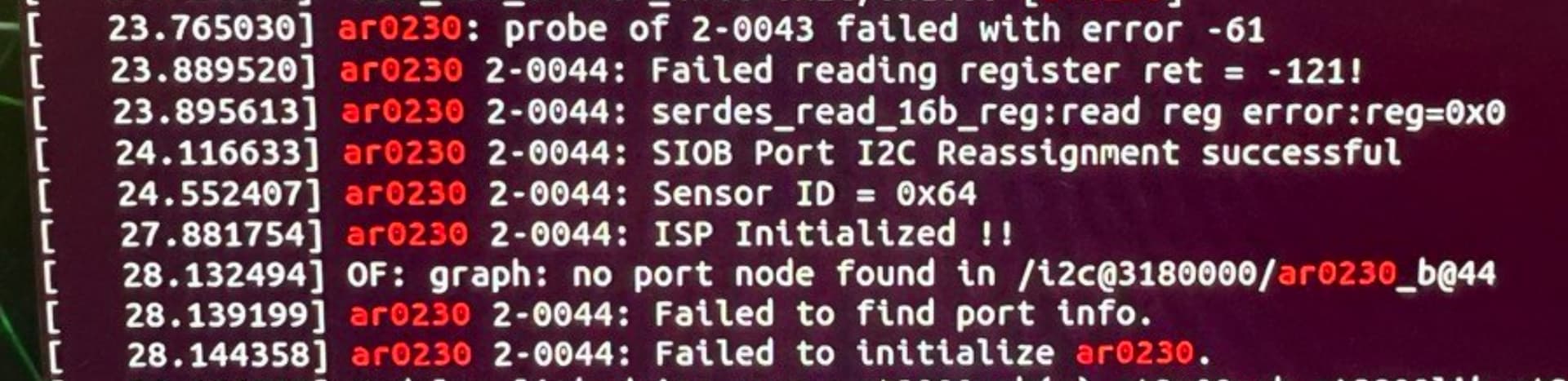
My previous approach was to modify the existing device tree file by MIIVII. The best result I have gotten to continue loading the existing video interface by MIIVII and also initialize the cameras in the device tree. The dmesg output is as follow - and it seems that the driver is able to detect the 2 GMSL cameras. However, something I am unsure here is the i2c address of the cameras, which I have set in the device tree as <0x43> & <0x44>, referenced from the e-con sample device tree. The desmg output makes sense, I didn’t link the port to the ar0230 device. (I tried doing that in the next approach but it couldn’t get it to work either). Dmesg Log & Device tree code:
tegra234-camera-max9296-a-nilecam-miivii-interface.txt (12.6 KB)
I have also tried to use method 2, writing up the virtual channel interface in the device tree. The .dtsi file is heavily referenced from the code provided by e-con to load the kernel driver for AR0230 (exact copy from e-con). All the necessary files for the virtual channel interface should be here, which includes tegra-capture-vi, nvcsi@15a00000, gpio@2200000, relevant interfaces in i2c@3180000 and tegra-camera-platform.
tegra234-camera-max9296-a-nilecam.txt (12.3 KB)
But initializing the MAX9296 chips with the original driver compatible = nvidia,max9296 seems to throw an error since I am unable to get the right i2c address … I have tried `<0x4>, <0x5> and <0x48> but they all don’t see to work. (dmesg log shown)
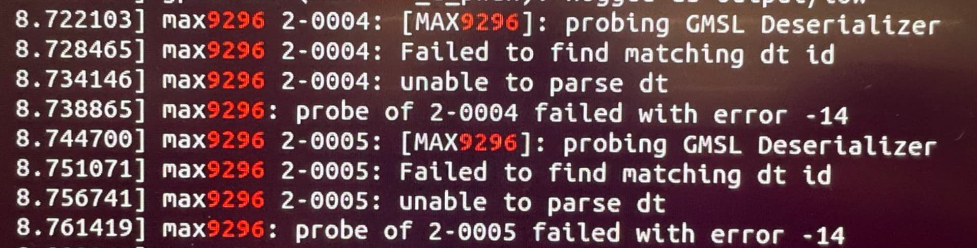
However, loading this device tree causes the Apex AD10 not to boot (the fan spins up for a long time > 1 minute) and then goes into a restart. If I were to disconnect the cameras, the Apex AD10 would boot fine. I am still trying to get the UART Debug port to work so I can see the boot log but to no avail … (but I will keep trying and post back if I get anything).
Additional note
If I used all the code from e-con and I connect the cameras, I do see 3 additional entries in the i2c-2 bus - 0x0e, 0x40 & 0x42. I presume that 0x42 is the MCU on the camera (stated in datasheet) and 0x40 is the serializer, but I am not sure what is 0x0e. However, when I connect 1 or 2 cameras, the addresses don’t change which I believe shows some collision in the i2c addresses? I am also not sure why my custom device tree doesn’t allow for the i2c addresses of the cameras to show up.
Also, if I connected 2 cameras on e-con deserializer board on a AGX Xavier Development kit, the addresses that show up in i2c-2 are: 0x0e, 0x0f, 0x41, 0x42 and 0x48. If I were to disconnect 1 camera, 0x0f and 0x42 would disappear.
Output of i2cdetect -r -y 2 on the Apex AD10, with ar0230 kernal driver loaded, and device tree copied exactly from e-con with no modifications (which is definitely wrong).
     0  1  2  3  4  5  6  7  8  9  a  b  c  d  e  f
00:          -- UU UU UU UU UU UU -- -- -- -- 0e --
10: UU UU -- -- -- -- -- -- -- -- -- -- -- -- -- --
20: -- -- -- -- -- -- -- -- -- -- -- -- -- -- -- --
30: -- -- -- -- -- -- -- -- -- -- -- -- -- -- -- --
40: 40 -- 42 -- -- -- -- -- 48 -- 4a -- -- -- -- --
50: -- -- -- -- -- -- -- -- -- -- -- -- -- -- -- --
60: -- -- -- -- -- -- -- -- 68 -- -- -- 6c -- -- --
70: -- -- -- -- -- -- -- UU
Summary of my questions which I hope someone could help me out!
- What are the i2c addresses of the MAX9296 deserializer chips? Are they the 4 addresses
0x40,0x4a,0x68and0x6c. If yes what is the0x04to0x11addresses? - What is the correct way to interface the cameras to the custom board. Should I follow the tegracam framework used by MIIVII or can I use the device tree with virtual interfaces? If I were to use the virtual channel with GMSL framework, do I initialize the MAX9296 chips with the default MAX9296 kernel driver?
- What is the i2c addresses of the GMSL cameras connected to the MAX9296 chip? e-con on their deserializer board uses
<0x43> & <0x44>, can I use the same too?
A few other questions which I hope to answer myself through more testing …
And will update the thread if I have the results.
- Modifying the device tree file so that the i2c addresses of the cameras show up.
- Why does the boot sequence get stuck when cameras are connected with the device tree loaded with the virtual channel with GMSL framework method. (will solve through getting UART debug).
I am pretty much out of things to try … and would take any suggestions on how I could make the e-con cameras work with this custom board. I have also probably sink way too much time into this, but I would really love to get this problem solved and be able to tell my housemate that “yay I am able to do device tree programming now!”. Previously I was telling her “yay I know how to compile out-of-tree kernels and device tree files” ;D