I am looking for a complete list of pin names and functions to make a custom 40 pin header map. I have read The Jetson Nano Developer Kit 40-Pin Expansion Header GPIO Usage Considerations, and other available questions. I want to bring used features out to the header for software testing prior to a complete carrier module. I am really looking to find a complete map of which pins and associated functions can be linked to the 40-pin header. The list available to the Python automation tools seems to be rather short. I expect there are limitations on some features which cannot be executed through your level shifter, but that most of the pin functions should be mappable to the header.
A pointer to the file that generates the base version of the 40 pin header would also be appreciated. The python tool generates overrides and I am looking for the underlaying mapping.
Thanks,
- - Scott Bonomi
Hi sbonomi,
Are you using Jetson Nano devkit or Orin Nano devkit?
What’s the Jetpack version in use?
Please share the result of the following commands on your board.
$ cat /etc/nv_tegra_release
$ cat /etc/nv_boot_control.conf
Have you tried using Jetson-IO tool to configure the pins on 40-pins header of the devkit?
This is a bit of a hybrid system at the moment. I have a Jetson Nano DevKit that came with an 8 Gig Memory. In order for my dev environment to match what we plan to deliver, We upgraded the Jetson Orin Nano module to a P/N 165-0877-000 which I believe is called the Jetson Orin NX.
When connected to the Host linux system it identifies as a 0955-7020 while operational. I am booting from a 256G NVME card and have a second NVME installed. I may have a disk mounting issue I need to correct before the next image load.
I want the system running from the 256GB disk. The 1TB disk is for data storage, and that was working properly on my Jetson Nano module when last mounted. I expect I missed a step when changing modules.
Most of the devices I have used over the years have several options for how each pin can be used and a large number of registers to set such that only the desired funcitons are enabled and active on the pins.
From reading the override files generated by the Jetson-IO tool, it seems that there are more options if the proper pin names are known and the associated function name identified. If I want to bring out the UART-3 TX and RX pins, to header pins already set up as I/O, It should not take a senior rocket scientist. I does take the appropriate documentation. The Carrier board we are going to build, has those brought out to an appropriate IC, but I desire to have a tested application sooner. Hand soldering to the pins on the module is not on my bucket list.
Regards,
-
- Scott Bonomi
gpu:~$ cat /etc/nv_tegra_release
R36 (release), REVISION: 4.3, GCID: 38968081, BOARD: generic, EABI: aarch64, DATE: Wed Jan 8 01:49:37 UTC 2025
KERNEL_VARIANT: oot
TARGET_USERSPACE_LIB_DIR=nvidia
TARGET_USERSPACE_LIB_DIR_PATH=usr/lib/aarch64-linux-gnu/nvidia
gpu:~$ cat /etc/nv_boot_control.conf
TNSPEC 3767-500-0000–1-1-jetson-orin-nano-devkit-
COMPATIBLE_SPEC 3767-000-0000–1–jetson-orin-nano-devkit-
TEGRA_BOOT_STORAGE nvme0n1
TEGRA_CHIPID 0x23
TEGRA_OTA_BOOT_DEVICE /dev/mtdblock0
TEGRA_OTA_GPT_DEVICE /dev/mtdblock0
gpu:~$
Jetson Nano(T210) and Orin NX/Nano(T234) are from totally different SoM series with different release.
From the result you shared, it seems are you using Orin NX 16GB(P3767-0000).
If you are developing the custom carrier board, Jetson-IO may not work since there might be custom design for the pins on 40-pin header.
I would suggest you configuring them through pinmux spreadsheet instead.
For the devkit, you can refer to the following figure in Jetson Orin Nano Developer Kit Carrier Board Specification .
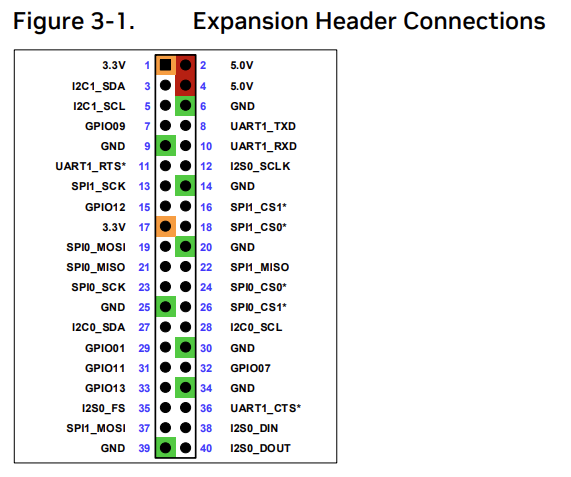
And the Table 3-3. for the list of pin mapping.

I am quite sure that any changes to the 40 pin header will not work on a custom carrier board, as we are not including that feature. We are including traces what will carry the signals to the appropriate level shifting ICs and on to the external interface connections as desired.
I believe that I should be able to redirect the UART0 Block from the Baseboard M.2 function to the Header40 while removing the SPI0 block from the Header40.
It is unclear at this time which function will wind up on which pin for the UART.
It would be nice to know where the processing steps after that are described. I have no great wish to listen to an hour video to get four lines of text commands
We don’t know the design of your custom carrier board.
What I shared is specific to the devkit board.
I think you have to check pinmux spreadsheet first to know what functions are available for each pins and configure them according to your custom design.
This topic was automatically closed 14 days after the last reply. New replies are no longer allowed.