Hi @walnut-Ree,
I would recommend pruning down your test data to the smallest scene that reproduces the issues, and try to separate the issues as well. It’s hard to see enough detail with the large meshes to make any educated guesses. Your first example with 16 tets should suffice.
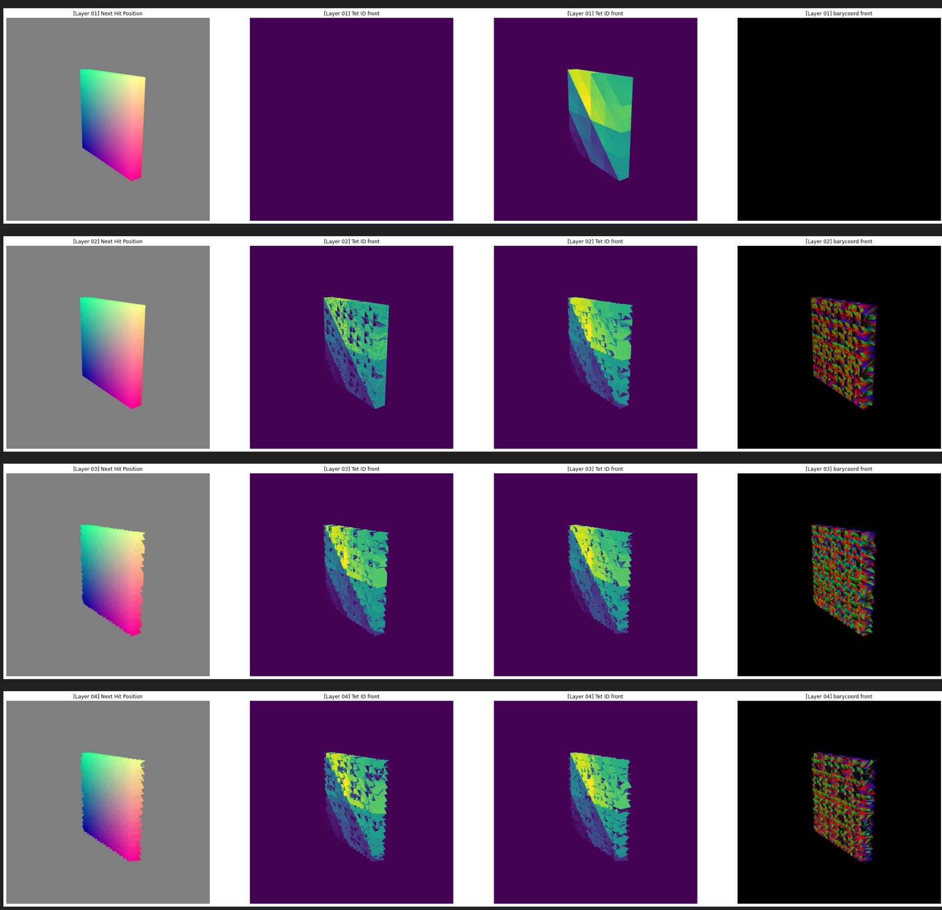
The first question is the noise. There are typically 3 reasons this happens, and you should take steps to carefully rule each one out. Assume these might be happening even if you don’t think it can, and then prove it doesn’t happen. 1) Your ray may be hitting two co-incident triangles. If so, the order they will be returned (or shaded via closest-hit) is undefined. Furthermore, because of your epsilon t_min, you would process only one of them and then skip over the other one. 2) You hit a triangle, then cast a new ray and, due to numeric precision, hit the same triangle again. If your epsilon is too small, then numeric rounding can put your ray origin randomly on either the closer side or the further side of the triangle, and the close ones can re-intersect. 3) There is random or uninitialized data being used during shading, or there is a mistake communicating values from the hit program back to raygen (e.g., failing to cast the uint payload back to float).
To rule out #2, you can easily turn up your EPS value and observe what happens. If the noise goes away, then the EPS value was too small. To rule out #1, you could export and inspect your model in a modeling package like Blender, or you could log your ray interactions using an any-hit shader and print out all your depth values along the ray. If you see two or more close or identical depth values, then you know you’ve got coincident faces. If you can prove it’s neither of those, then rule out shading by first removing any variables (for example return a constant solid color if hit - this is also a good way to implicate #1 or #2.)
For the background triangles, first verify using any-hit or shading that something is actually being hit by a ray for those pixels. If something is being hit, it’s because it is in your BVH. If not, then it could look like triangles because of the way the background shading is being done. Those are the only two possibilities, so you can use that knowledge to go to the next step in verification. One possibility is that you might have vertices in your mesh with unexpected coordinates for some reason. This could happen if you tell OptiX you have more vertices in your vertex buffer than you provide, so check all array bounds. It could also happen if you compute vertices on the fly and some of them blow up and you didn’t notice. This is another good reason to export the mesh and inspect it outside of your application.
I find it very useful to implement mouse-based debugging, and I think it could help you. You can add a click handler to your application, then set the click coordinates and a boolean debug flag in your optix launch params. Then when you launch, you can print debug output for only the rays where the optix launch id matches your click coords. This makes it easy to limit the debug output to a manageable amount and to have control over which pixel / ray / object you want to inspect. Just to plant a seed in your head, sometimes I will do things like printf the ray and the vertices of all the triangles the ray touches in OBJ format, save the output to a file, and then inspect the result in Blender using OBJ import. This kind of thing is very powerful, and also surprisingly easy to implement.
–
David.