Hi Jerry,
I have defined the port bindings in device tree file, but it didn’t work.

hello wangkun37,
please see-also reference driver for using GMSL chips,
such as.. $public_sources/kernel_oot_modules_src/hardware/nvidia/t23x/nv-public/overlay/tegra234-p3740-camera-p3783-a00-overlay.dts
Hi Jerry,
I refer nvidia imx390 dts and driver, and config serdes register manually, now the /dev/videoX node can create successfully. But when I test the video capture use the v4l-ctl command, it can’t work, and the kernel print VI error, please help me to analysis that, thank you.

hello wangkun37,
you may try to revise the v4l pipeline to assign sensor supported resolution, image formats,
for instance, $ v4l2-ctl -d /dev/video0 --set-fmt-video=width=1920,height=1080,pixelformat=UYVY --set-ctrl bypass_mode=0 --stream-mmap --stream-count=100
besides.. it’s reporting that capture has timed out.
please double check it’s sending camera frames onto CSI channel correctly.
Hi Jerry,
I have check the max96717 register 0x112, it’s value is 0x8a, that means the serializer has receive the camera data. And the camera real resolution is 2560x1440 25fps YUV422-8bit, how can I fix the v4l2-ctl list-format to right value? Thx!
hello wangkun37,
v4l2-ctl list-format check the sensor driver side to report the details.
let me take IMX274 as an example,
$public_sources/r36.4.3/Linux_for_Tegra/source/kernel_oot_modules_src/nvidia-oot/drivers/media/i2c/imx274_mode_tbls.h
there’s imx274_frmfmt to list all available sensor formats.
for instance,
static const struct camera_common_frmfmt imx274_frmfmt[] = {
        {{3840, 2160}, imx274_60_fr, 1, 0, IMX274_MODE_3840X2160},
        {{1920, 1080}, imx274_60_fr, 1, 0, IMX274_MODE_1920X1080},
        {{3856, 4448}, imx274_30_fr, 1, 1, IMX274_MODE_3840X2160_DOL_30FPS},
        {{1936, 2264}, imx274_60_fr, 1, 1, IMX274_MODE_1920X1080_DOL_60FPS},
Hi Jerry,
With the ADI FAE support, the max96724 CSI Controller1 has send camera data to orin CSI module, and I have config the port-index correct refer the tegra234-p3737-camera-fzcam-fg12ch-4lanes.dts file. But when I capture by use v4l-ctl command, the VI error again. How can I do to resolve the issue? Thank you!
hello wangkun37,
is the v4l2-ctl list-format report the correct sensor supported formats?
may I know what’s the your test pipeline, and what’s the error messages?
hello wangkun37,
it’s a bad practice for pasting the logs as a picture.
I’ve notice there’s an invalid argument error has reported from your v4l pipeline.
besides, your sensor driver also reporting an error of updating control range.
please debug into your driver side.
Hi Jerry,
Actually, my camera is in YUV format and does not need to configure the initialization configuration similar to the RAW camera. Can these configurations be removed?
Hi Jerry,
The v4l2-ctl list-format has report the correct sensor supported formats. Add the kern.log when I excuse the command: v4l2-ctl -d /dev/video1 --set-fmt-video=width=2592,height=1944,pixe
lformat=UYVY --stream-mmap --stream-count=100
kern_0616.log (79.4 KB)
tegra234-p3737-camera-fzcam-fg12ch-4lanes.dtsi.0616.txt (11.0 KB)
hello wangkun37,
below properties of the GMSL link looks incorrect.
					gmsl-link {
						src-csi-port = "b";
						dst-csi-port = "a";
						serdes-csi-link = "b";
						csi-mode = "1x4";
						...
for instance,
you should set dst-csi-port to CSI-E as it’s the actual destination CSI port on the Jetson side.
please double check developer guide for reference.
Hi Jerry,
Good news, whe I test video0, it can work successfully.

But what I confused is that there is only one camera module connects with board on GMSL B, In theory, the video1 should work, and the video 0 should not work. What’s the reason? Thank you!
hello wangkun37,
it’ll find a available number to register the video node automatically, which start from video0 by default.
FYI, during kernel initialization stage, it’s step for camera device registration to setup a video device node to linux kernel. sensor probing only run once during kernel initialization stage of system boot-up.
for a typical camera application running cycle, the driver will Power On the sensor, Start Sensor Streaming, sending relevant v4l2 controls, and finally power off the sensor.
so… it’ll register a video node, (/dev/video0) if there’s no error returns.
Hi Jerry,
Thanks for you kindly response. Now I test GMSL A and GMSL B at the same time. The ADI FAE has provided the correct serdes registers configs, but when I test capture with v4l2-ctl, the VI report error, both video0 and video1 has the same issue.

If you want more kernel logs, I will provided. Thx a lot!
please see-also Topic 318537 to debug the discarding frame corr_err messages.
Hi Jerry,
With ADI FAE help, the Deserializer’s ERRB is bandwidth cause, and I optimized the 0x418 register has resolve the ERRB error. And I increase the pix_clk_hz from “74250000” to “151165440” in dtsi file. But I test again, the video 0 and video 1 show different type issue. How can check next? Thank you!

Hi Jerry,
When I change the serdes_pix_clk_hz from “375000000” to “125000000000”, the VI not report error, But when I test preview by gst-launch-1.0 tools, the image is black picture. Please help me analysis it. Thanks!
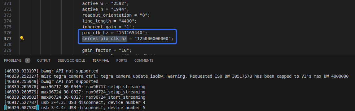
hello Kevin_Wang2025,
is there a typo? it is 125 Ghz per your settings.
please double check developer guide, SerDes Pixel Clock to evaluate your clock rate.
Hi Jerry,
My deserializer data rate per lane is 2300 Mbps, 4 lanes , 16 bits per pixel,
and I calculate pixel_clk_hz by the formula:
pixel_clk_hz = sensor data rate per lane (Mbps) * number of lanes / bits per pixel,
so pixel_clk_hz = 2300 * 1000 *1000 * 4 / 16 = 575000000, is that right?
And I calculate serdes_pix_clk_hz by the formula:
serdes_pix_clk_hz = (deserializer output data rate in hertz) * (number of CSI lanes) / (bits per pixel),
so serdes_pix_clk_hz = 2300 * 1000 *1000 * 4 / 16 = 575000000, is that right?
Thank you!