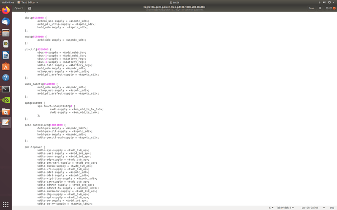
I used the TX2 flashed by Jetpack4.3 before. At that time, we also encountered the problem that the usb could not be recognized on the board we designed. After that, we replaced the two .dtb files and then flashed the usb again and the problem was solved. Now I need to use TensorRT8.0, so I use jetpack4.6 to flash TX2. After the flashing is completed, I find that the usb cannot be used, but the network port eth0 is normal. Then I replaced the two .dtb files and flashed the device again to find that the usb can be recognized normally. But the network port eth0 can’t be used. Is there any way to help me solve this problem?
Did you update the device tree for your board’s layout? If not, then this is why. Check out the “bring-up” guide here:
https://developer.nvidia.com/embedded/downloads#?search=bring-up&tx=$product,jetson_tx2
Also, for the spreadsheet with macros to generate configurations, see the PINMUX document here:
https://developer.nvidia.com/embedded/downloads#?search=pinmux&tx=$product,jetson_tx2
The gist is that the device tree tells the module how the carrier board pins/traces are routed, and that the default flash software expects the dev kit layout. Unless your carrier is an exact match to the dev kit, then you will find some missing functionality.
You cannot just directly pick up dtb from jetpack4.3 to jetpack4.6…
DTB needs to follow the kernel … Since jetpack4.6 has different kernel with jp4.3, hitting an error is under expectation.
How should I modify the device tree to solve the USB problem? Is there any specific documentation to refer to?
The bring-up guide above is such documentation, and the PINMUX spreadsheet (once macros are enabled) is a tool to generate this based on your selection of devices/trace routes.
please refer to the adaptation guide. You can find it over the developer guide.
I set up a cross-compilation environment, modified the contents of the tegra186-quill-power-tree-p3310-1000-a00-00.dtsi file as shown in the figure below, then I recompiled the dtb, and finally updated the device tree with the falsh tool. In the end, I found that the usb can be used on the development board, but it still can’t be used on our custom board. Below is the kern.log of the TX2 launching on our custom board. Please help me to find out what is wrong?
kern.log (951.7 KB)
syslog (2.2 MB)
You can firstly learn how to attach useful information.
For example, if you want to share what you’ve modified, share it as a diff text file. Do no share any “picture” for logs. It is really not helping situation. Picture is always truncated.
And if you want to share kernel log, just share one time boot log. We don’t want to check a log with many boot iterations.
Also, if you want others to help “custom board” issue, attach your schematics. We are not your colleagues so will not know your board design. The device tree has to match the board design. Currently, you are just asking some strangers who don’t even know any details to help you.
Here’s what I did to decompile some dtb files. However, it is still not usable to put usb on our own customized version.
JP4.3自己反编译的dts.zip (109.0 KB)
JP4.6_自己反编译的dtb.zip (116.8 KB)
JP4.6自己反编译的dts.zip (112.8 KB)
log.zip (63.8 KB)
Did you ever read the document or not?
FYI, the device tree is custom to each carrier board. The tree you would use would be provided by the custom board vendor (if that is you, then it comes back to the adaptation guide). I would not expect the same tree to work on both the dev kit carrier board and the custom board unless all wiring layout is an exact match. I saw “elroy” in there…is this an elroy carrier board? If so, does the manufacturer have a device tree for this? If that is the case, then you probably would not need to compile a tree.
This topic was automatically closed 14 days after the last reply. New replies are no longer allowed.


