Hi, I am trying to get GPIO level in UEFI boot flow. Because I want to use gpio to select boot Mode or use
GPIO to select the boot device. Is there any reference?
Kind regards
Bryan
Hi, I am trying to get GPIO level in UEFI boot flow. Because I want to use gpio to select boot Mode or use
GPIO to select the boot device. Is there any reference?
Kind regards
Bryan
Hi Bryan_Zhong,
You could use https://github.com/NVIDIA/edk2/blob/main-edk2-stable202208/EmbeddedPkg/Include/Protocol/EmbeddedGpio.h protocol to read the status of a GPIO.
and the usage just like the example (https://github.com/NVIDIA/edk2-nvidia/blob/main/Silicon/NVIDIA/Drivers/TegraGpio/TegraGpioDxe.c).
You could also refer to https://github.com/NVIDIA/edk2-nvidia/blob/r35.3.1-updates/Silicon/NVIDIA/Application/GpioUtil/GpioUtil.c#L151 to see how we get the interface to embedded gpio protocol.
Same file then has the interface reference to function pointers for GPIO operations
Thank you for all your assistance.
Hi KevinFFF,
After I check the source code of GpioUtil.c and TegraGpioDxe.c .There is still something makes me confused.
When I run GpioUtil.efi, I don’t know how to get the specific ‘gpio id’.
According EmbeddedGpio.h,it seems like the 'gpio id ’ is like this :

I don’t know how to get the port number.
Is there any reference? Or can you give me an example?
Thanks.
The gpio id is a 4 Bytes number out of which higher 2 bytes are phandle of gpio controller and lower 2 bytes are gpio number for that controller.
It should be as the following macro, and you could refer to tegra234-gpio.h for port.
#define GPIO(Port, Pin) ((EMBEDDED_GPIO_PIN)(((Port) << (16)) | (Pin)))
#define TEGRA234_MAIN_GPIO_PORT_H 7
You should also check the dtb for phandle, which is generated at compile time.
Or you could just pull high/low for your desired pin externally and print the result in UEFI to check which gpio-id are you using.
I will check this later.
and I feel confused that it seems like only two port ‘0xB and 0xC’. and the port 0xB have 0xD9 pins ,the port 0xC have 0x26 pins.
The gpio-id in UEFI is just like I mentioned in the previous reply.
I think one is from MAIN GPIO controller and another is from AON GPIO controller.
This is the phandle, please also decompile the dtb you are using to check its value.
I have tested the input function.It is ok.

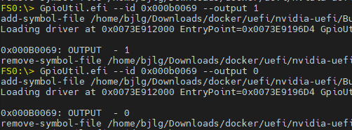
But when I test output function. I found that even if I set GPIO27(PN.01) to 1(high-level),the output level of gpio27 is unstable,most time it is still low.
but my colleague says that it may need a pull-up resistor.
Is it right?
Thank you so much!
Have you tried to use sysfs to control this pin (PN.01) with the same issue?
and what do you mean “most time”? Do you mean it could be controlled as expected sometimes?
Yes,it is.I set GPIO27(PN.01) to 1(high-level) successfully twice. But I cannot repeat it now.
I try it just now and find that it is ok by using sysfs to control this pin (PN.01).
I also tested GPIO35(PG.00).The test results are the same. when using sysfs to control these pin,output function and input function are both okay. But when I tested it in UEFI,the input function is okay. the output function is wrong. I can not set these GPIO to output high level in UEFI.
When I tested GPIO27(PN.01).I used gpio-id 0x000B0069.
When I tested GPIO35(PH.00).I used gpio-id 0x000B0038.
Does your use case also need to configure some pins to high?
Are you testing on the devkit or custom board?
Would that work in your case?
I don’t try it yet.
It would be better if gpio pin can be configured to high in UEFI. Thus we can use gpio level as a feedback signal in UEFI.If not ,it is also ok. we can give feedback after system booted.
I am testing on the devkit.
It seems both of these pins configured as input as default in pinmux.
Could you help to update pinmux to configure them as output before control them in UEFI?
I have never done this before,But according Linux_for_Tegra/kernel/pinmux/t19x/README.txt, I generated jetson_agx_industrial.cfg file. I don’t what I should do next. Any suggestion?
I know some information from forum.The next step is to replace cfg and reflash. But which file should be replaced?
Thanks.
Problem solved.
It is okay after updating pinmux to configure them as output .They can be controlled as expected.
But the input function is not okay now. That means the direction of gpio can not be changed in UEFI.
Thanks.
This topic was automatically closed 14 days after the last reply. New replies are no longer allowed.


