GPIO reading input issue

Hi,

I have an issue reading an input on my Jetson Orin Nano. As I need to run a C code because of other libraries, I use the following library: GitHub - Rubberazer/JETGPIO: C library to manage the GPIO header of the Nvidia Jetson boards (which I have successfully used before).

When I press a button, I send a PWM (servo) signal to pin 15 of my Jetson Orin Nano. I am aware that the library has no function to read PWM, but I was able to write a custom code that worked with another system. I registered an ISR function that is supposed to be called and read the PWM. Currently, the ISR is never called. I made another test code using gpioRead() to print the pin level in the terminal and there is no change when I press the button. Finally, looking with an oscilloscope, I can see the PWM signal, but it is only 300mV at high state when connected to the Jetson. When my remote controller is not connected to the Jetson, the PWM signal level is fine.

I don’t think the issue is related to the library itself, but rather a configuration pin issue. I checked the PINMUX spreadsheet, and if I understand correctly, pin 12 is GPIO 15 which is configured as PD as initial state. I guess that I need to change it to Z, right?

First of all, if there is any other pin I can connect to that has directly the right configuration, I am happy to change it.

Otherwise, I understand I need to change the initial state of the pin in the spreadsheet and then apply these updates to the Jetson. I am really confused about how to do that, this is something totally new for me. First, the spreadsheet contains two sheets: which one should I use? Then, I see I can generate 3 .dtsi files, but what are the next steps?

Thanks a lot

Hi,

I don’t think it’s about pull up/down because this pin is by default configured as GPIO but not PWM.
https://developer.nvidia.com/downloads/jetson-orin-nx-and-orin-nano-series-pinmux-config-template

We have documents on how to flash with customized pinmux setting:
https://docs.nvidia.com/jetson/archives/r36.3/DeveloperGuide/HR/JetsonModuleAdaptationAndBringUp/JetsonOrinNxNanoSeries.html#mb1-configuration-changes

Thank you for your reply, I will try to change the configuration today anyway.

If you don’t think pull-down is the issue, do you have any other suggestions?

I’m saying it’s about the difference between GPIO/PWM.

Ok I see. In my application, I want to read a PWM signal, so I think the pin should be in GPIO mode, no? And if I understand correctly, this should be the case by default…

GPIO is not the same as PWM…
PWM needs hardware suppport, and while you can use a GPIO pin to act as PWM, it’s only software simulation and not as precise as real PWM.
The pinmux spreadsheet gives you the option to config the pin as PWM.

Yes thank you, I understand that.

But I thought this applies only when you want to generate a PWM as output, while I want to read a PWM coming as input to the Jetson. But maybe I am confused and the pin has to be set as PWM also for reading?

YES, it should.

Ok, thanks a lot for the clarification.

We enabled pin 15 as PWM using

sudo /opt/nvidia/jetson-io/jetson-io.py

But we still have the same weak signal with the oscilloscope.
Do you think we should using the spreadsheet instead?

Please update the pinmux spreadsheet and re-flash the device.

Will do that and let you know.
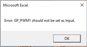
I am just a bit confused (again), because if I set the pin as GP_PWM1, it can only be an output. So will it be possible to read the PWM signal?
And what should be Req. Initial State?

spreasheet_error

Thanks again for your help

Oh, OK.
So I might be wrong.
Can you please first confirm if a normal GPIO, instead of PWN, signal is sent to the pin, then is the voltage read correctly?

Yes, we set pin 18 as output and pin 15 as input. We physically connected them together, and when we put pin 18 as 0 or 1, pin 15 is driven correctly. This code was using the library we want (GitHub - Rubberazer/JETGPIO: C library to manage the GPIO header of the Nvidia Jetson boards)

Can you make sure there is no other driver occupying this pin?
Probably it’s pulled low by some other programs.

This is the output of

sudo cat /sys/kernel/debug/gpio

Then can you please check status of pin 15 and pin 18?
I cannot really tell them from your screenshot.

Sorry for that, I struggled to find the right command
Please find the output of

cat /sys/kernel/debug/gpio

If I understand correctly, pin 15 is PN.01 and pin 18 is PY.03, so both look not in used to me

gpio_status.txt (6.7 KB)

Do you have any other suggestions?

For debug purpose, I am trying to dynamically change pin config using

busybox devmem

From my research, the address of pin 15 (GPIO12/SOC_GPIO39) is 0x02440020

I am trying to find the right configuration (bits value) for our application.

I was thinking of 0x040 for our application. Could you confirm please?

Thank you for your help!

Pin 15 is PN.01 and pin 18 is PZ.06.
Anyway, they are both not used.

It depends on the original value, and you just modify required bit fields.
See more detail here:
https://docs.nvidia.com/jetson/archives/r36.3/DeveloperGuide/HR/JetsonModuleAdaptationAndBringUp/JetsonOrinNxNanoSeries.html#changing-the-pinmux

This topic was automatically closed 14 days after the last reply. New replies are no longer allowed.