I2c7: I2C transfer timed out; i2c bus no longer functional

Board: Jetson Nano Application Processor (8GB RAM) and SOC Development Board (945-13766-0000-000‬)

We were testing several sensors with i2c bus 7 a few days ago and everything appeared to be functioning fine with the sensors showing up, and being capable of receiving and responding to commands.

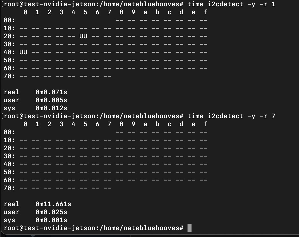
We’ve tried again today and keep getting a slow scroll on i2cdetect and repeated “I2C transfer timed out” entries for i2c bus 7 (c250000). We’ve confirmed the sensors are functional and not causing issues as connecting them to i2c bus 1 works perfectly fine.

Support asked us to post a topic here to get verification of the issue from forum staff for requesting an RMA, but I’m happy to troubleshoot further as needed to try and get it working again.

  1. Probe the i2c signal to confirm the signal is in right status.
  2. Reflash the system by sdkmanager.

Hi ShaneCCC,

We’ve reflashed the system to a fresh SD Card with Jetpack 6.2, but still getting the same error. We’re waiting on a scope coming in to probe the i2c bus, and I’ll get back once we’ve got that!

Hi @ShaneCCC,

We’ve got a logic analyzer in and checked both i2c Bus 7 and Bus 1. We’re able to see and decode i2c traffic (from i2cdetect) on Bus 1, but Bus 7 appears to be giving out <1V and not signaling when using i2cdetect.

Bus 1

Bus 7

Is there anything else you’d recommend for troubleshooting?

Please check why I2C bus 7 is not showing correct voltage levels. Common issues to check for are voltage incompatibility between the I2C bus on the module and on the sensor/device. Any voltage translators used on the I2C bus? Check the pull-up resistors are used on I2C SCL and SDA lines on both sides of the voltage translator/level shifter, if used and fine tune them, if needed to meet I2C specifications. Capture scope shots to verify the signal voltage levels and and timing.

@sgursal We’re not using any voltage translators on the i2c bus. The above pictures in the previous message were also performed with no external devices on the i2c bus 1 or 7.

Bus 7 had no devices at the time we probed and i2cdetect slowly prints out each entry with a - and generates “I2C transfer timed out” with every attempt. We get 0V from SDA / SCL.

Bus 1 appears to have internal i2c devices taken by the Jetson itself, and works fine with correct voltages and traffic on the i2c bus. Bus 1 has the correct voltage level and signals correctly with the internal i2c devices and our external i2c sensors (with pull-up resistors).

Please attach a suitable I2C device and see if you can access or read/write to it. Also, is the I2C Bus 7 configured to use as I2C in the pinmux? If configured as GPIO then I2C access will not work. Are you using custom carrier board? Other option will be to test it on our dev kit and see if it works as expected.

@sgursal Yes, it’s configured via /opt/nvidia/jetson-io/jetson-io.py as I2C not GPIO.

Here is output from i2cdetect on both buses along with time the operation took:

We are currently using the Jetson Orin Nano Super Developer Kit with the NVIDIA provided carrier board. The I2C device connected doesn’t initially show up in i2cdetect, but communicates correctly via Bus 1, but no communication via Bus 7 and we still get 0V probe.

On 40 pin expansion header pin 3 and pin 5 what is the voltage level you are getting/measuring when I2C bus is not in use?

We’re getting 0V when devices are connected to Bus 7, and when no devices are connected, we get 0.005V on I2C1_SDA, and 0.011V on I2C1_SCL

Clarification: Also measured Bus 1 and I2C0_SDA provides 3.3V and so does I2C0_SCL

Please share the result of the following commands on your board.

$ cat /etc/nv_tegra_release
$ cat /etc/nv_boot_control.conf

Do you have another board with similar issue to clarify if the issue is specific to current board?
If so, have you tried to configure these 2 pins (PDD.01/PDD.02) as GPIO and check if they can be controlled or they are damaged?

Could you also share the full dmesg for further check?

@KevinFFF, sorry about the delay – Didn’t get a notification for this reply.

Please share the result of the following commands on your board.

$ cat /etc/nv_tegra_release

# R36 (release), REVISION: 4.3, GCID: 38968081, BOARD: generic, EABI: aarch64, DATE: Wed Jan  8 01:49:37 UTC 2025
# KERNEL_VARIANT: oot
TARGET_USERSPACE_LIB_DIR=nvidia
TARGET_USERSPACE_LIB_DIR_PATH=usr/lib/aarch64-linux-gnu/nvidia

$ cat /etc/nv_boot_control.conf

TNSPEC 3767-300-0005-R.1-1-0-jetson-orin-nano-devkit-super-
COMPATIBLE_SPEC 3767--0005--1--jetson-orin-nano-devkit-super-
TEGRA_BOOT_STORAGE mmcblk0
TEGRA_CHIPID 0x23
TEGRA_OTA_BOOT_DEVICE /dev/mtdblock0
TEGRA_OTA_GPT_DEVICE /dev/mtdblock0

We have a Raspberry Pi 5 that works with these sensors, but we don’t have another Jetson to test with. I am reprogramming the affected I2C pins to GPIO now and will check with the logic analyzer / probe to see if they’re functional – I will have update shortly.

dmesg.log (58.1 KB)

It more than likely died, we were stress testing it and had all the ARM cores and GPU maxed out while capturing i2c data looking for missed data. Well, the i2c blew out in less than 24 hours. Sent the board back and have not been able to get a replacement so we can resume testing.

The GPIO on the board is a lame set up, you need to take special care with the gpio and use a line driver and if memory is correct, the i2c bus needs a level shifter if you have 5v on it. The SoC is 1.8v and they have a level shifter on board to 3.3 so this is all from memory so don’t take if for fact. You will need to do your home work on this.

Do you mean that there’s no signal output on scope when you run i2cdetect for bus 7?

I don’t see any error relating to c250000.i2c in the dmesg you shared.

Please share us the result if you’ve configured them as GPIO and check if you can control them.

Yes, there’s 0V detected when we run i2cdetect on Bus 7, but 3.3V plus i2c traffic when run on Bus 1.

Apologies.. I hadn’t re-run i2cdetect before getting that dmesg. Here’s one with i2cdetect having been run and the resulting dmesg log:

jetson-log-i2c-dmesg.log (66.7 KB)

We followed the guide here to try to create a custom overlay to change them to GPIO, but we’re not able to get it to work (still seeing 0V).

Here’s the DTS we’re trying to use, could you let us know if we’ve done something wrong?

test.dts

/dts-v1/;
/plugin/;

/ {
jetson-header-name = “Jetson 40pin Header”;
overlay-name = “User Custom [2025-05-27-164945]”;
compatible = “nvidia,p3768-0000+p3767-0000\0nvidia,p3768-0000+p3767-0001\0nvidia,p3768-0000+p3767-0003\0nvidia,p3768-0000+p3767-0004\0nvidia,p3768-0000+p3767-0005\0nvidia,p3768-0000+p3767-0000-super\0nvidia,p3768-0000+p3767-0001-super\0nvidia,p3768-0000+p3767-0003-super\0nvidia,p3768-0000+p3767-0004-super\0nvidia,p3768-0000+p3767-0005-super\0nvidia,p3509-0000+p3767-0000\0nvidia,p3509-0000+p3767-0001\0nvidia,p3509-0000+p3767-0003\0nvidia,p3509-0000+p3767-0004\0nvidia,p3509-0000+p3767-0005”;

fragment@0 {
	target = <&pinmux>;

	__overlay__ {
		pinctrl-names = "default";
		pinctrl-0 = <0x01>;

		exp-header-pinmux {
			phandle = <0x01>;

                            hdr40-pin3 {
                                    nvidia,pins = "gen8_i2c_scl_pdd1";
                                    nvidia,function = "rsvd1";
                                    nvidia,tristate = <0x00>;
                                    nvidia,enable-input = <0x00>;
                            };

                            hdr40-pin5 {
                                    nvidia,pins = "gen8_i2c_sda_pdd2";
                                    nvidia,function = "rsvd1";
                                    nvidia,tristate = <0x00>;
                                    nvidia,enable-input = <0x00>;
                            };
		};
	};
};

};

Okay, I see so many I2C timeout messages as following.

[95841.165405] tegra-i2c c250000.i2c: I2C transfer timed out
[95841.269383] tegra-i2c c250000.i2c: I2C transfer timed out

Please configure them in pinmux spreadsheet as following and reflash the board to apply change.
image

After boot up, you can simply run the following commands to control them.

# gpioset --mode=wait `gpiofind "PDD.01"`=0
# gpioset --mode=wait `gpiofind "PDD.01"`=1
# gpioset --mode=wait `gpiofind "PDD.02"`=0
# gpioset --mode=wait `gpiofind "PDD.02"`=1
1 Like

This topic was automatically closed 14 days after the last reply. New replies are no longer allowed.