Jetson Nano UART TX Pin (Pin 8 J6 Header) corrupts characters

Hi, as part of a university robotics project I am required to communicate between a Jetson Nano and some kind of microcontroller (to be used for 5+ PWM channels) over UART on pins 8 and 10 on the 40 Pin header. When attempting to do so I can successfully receive clear data on the Jetson, however when trying to transmit from the Jetson all sent data is corrupted(shown in the bellow image).

Jetson-CH340G
Jetson TX Pin corrupted strings

This particular image was generated by plugging the serial output of the Jetson into a serial to usb adapter with a CH340G chip and opening the serial port using PuTTY on my laptop (Win10).

Setup:

  • Pin 8 TX connected to RX on CH340G
  • Pin10 RX connected to TX on CH340G
  • GND connected to GND
  • port opened using Pyserial library at baud 4800 with all other default settings on both Jetson and Laptop
  • using /dev/ttyTHS1

This output was produced using the following program on the Jetson

import serial

baud = 4800

ser = serial.Serial('/dev/ttyTHS1', baud)
print(ser)

try:
    while True:
        ser.write(b'H')

except KeyboardInterrupt:
    print("closing...")

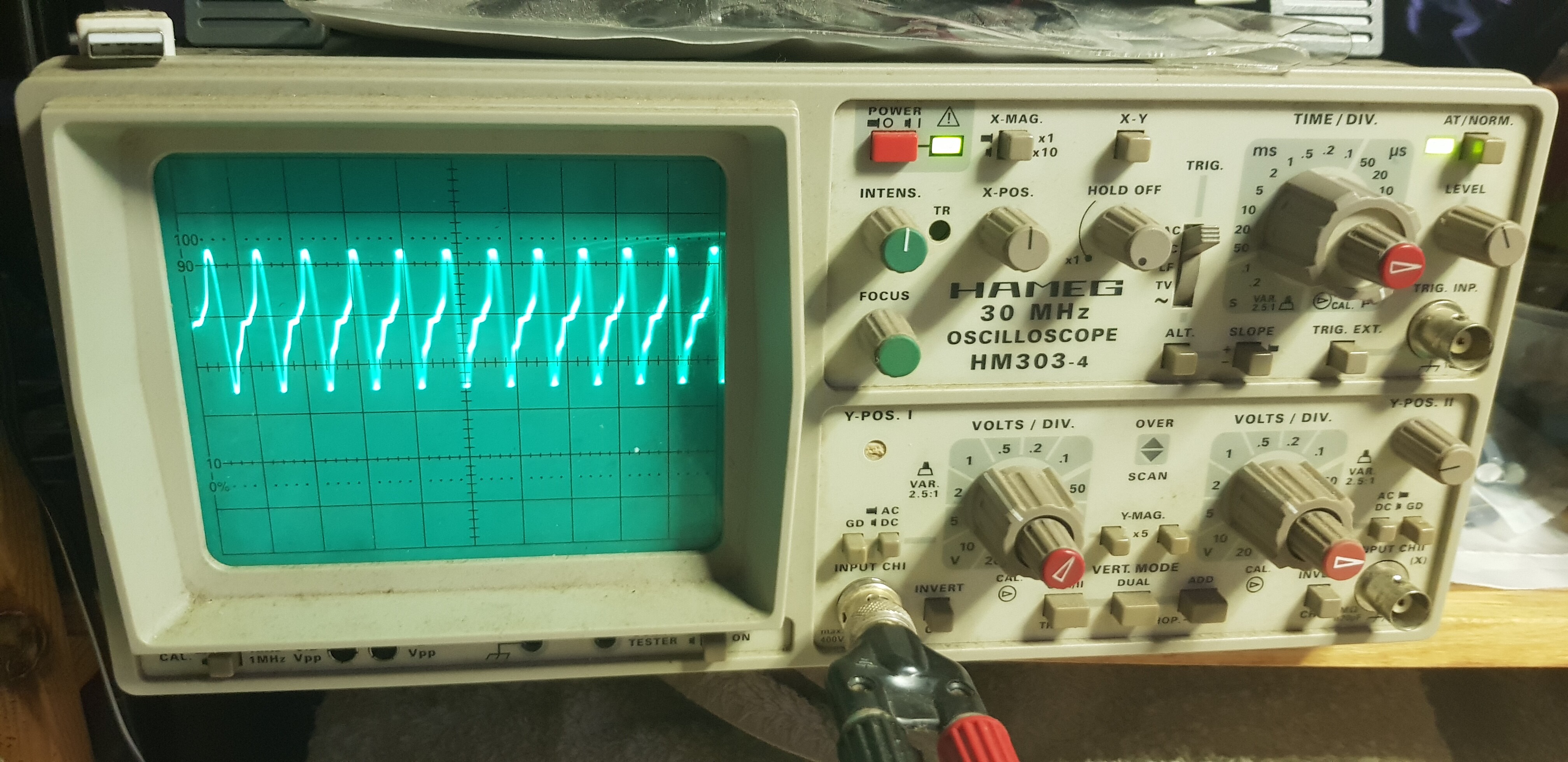
I had a look at this on an oscilloscope both at just over the TX pin and ground with nothing connected, which shows it working, and over the TX pin and ground while the TX pin is connected to the CH340G which is known to fail.


The J40 TX Pin with working nothing connected, and GND


The J40 TX Pin connected to the CH340G producing a corrupt output on the serial monitor, and GND.


Setup used to probe over the connection to the CH340G

Devices that I tried:

  • CH340G failed
  • ESP8266 failed
  • RP2040 failed
  • Pi Zero W however was successful in receiving clear UART data from the Jetson

Measures Taken:

  • nvgetty is disabled.
  • The grounds of the Jetson and each device iv tested it with were connected
  • I’ve tried Baud rates ranging from 115200 down to 120 and seen no improvement. The majority of my tests have been at 4800 which did clear up some corruption in receiving on the Jetson as opposed to 9600 but had no effect on the scale of corruption when receiving.
  • All other devices I tested the Jetson with were able to successfully send and receive UART data to/from my laptop.
  • All devices run on 3.3V

This is further to the bellow similar issues, it has also been reported on the NX using the same carrier board. The only solution suggested in the bellow threads is to circumvent the issue by connecting one of the Jetson’s USB ports to a USB to serial adapter to provide a serial interface a side from the one on the 40pin header. Although this is not ideal to me as I have limited use of USB ports on my board.

Hopefully with the additional information here we may get a step closer to finding the problem.

Someone else will probably have to help, but I am wondering what happens if the line with corruption has a 10k resistor added between that pin and ground (a pull-down)?

I am also seeing, in the oscilloscope image, what looks like the TX which fails as being a much higher frequency than the RX (as if there is a much higher frequency setting in combination with a lower setting which is a mix of the expected rate and a much higher rate). If you use the default speed of 115200 8N1, does the part of the corrupt TX appear to somewhat go away, with the TX and RX rates looking like they are entirely a single frequency and not a blend of a lower and higher frequency?

Hi, I haven’t tried the 10k pull down yet, it is a suggestion I’ve seen and hopefully will get around to testing it in the morning. (Im currently occupying 3 of 3 official roles on this project so things move slowly at the moment) Not sure what you mean RE the oscilloscope images, they are both showing the TX pin and ground, the top working one shows the TX pin using 3.3V and 0V levels to signal b’H’. There is no activity on the RX pin as I’m not receiving anything in this test.

Ok, I see that they are both TX. However, take a close look at the top image…this and the lower image have basically the same output for the low frequency part of the spectrum. All of that extra “filler” on the lower image appears to a much higher frequency. That could conceivably be a mix of the “correct” content along with a much higher data rate content. If you were to increase the scan rate of the signal displayed in the lower image, then it would be quite useful to know if the “extra” turns out to look like a clean square wave signal (like the lower frequency content), but higher frequency, versus looking like noise.

If the signal has both correct and incorrect speeds, then it is possible the two sides of that particular pin are merely set to different data rates. Or that something else is mixing in.

If you had two signals on that pin, and if those frequencies are independent, and if the lower frequency is the expected signal output, then as you increase the “expected” signal rate via settings to the UART, then the two frequencies should merge. My concern is that the issue is a mismatch of a setting in the TX side of the Jetson UART, rather than being a hardware issue.

So, I’ve gotten around to looking the above suggestions. The interference when the signal should be 0V is a continuous wave form at around 10Mhz (my evening napkin maths so please check this if you think its anything, division is 0.1 micro seconds). Definitely doesn’t look like signalling at a much high baud.

Tried pulling down with a 10k resistor with the bellow setup

With the CH340G connected it produced a very similar output, and all corrupt characters on the serial monitor

I was also able to get a closer look at it with a logic analyser, although it seemed to be inverted, the wave form was very unstable, some peaks could hold 3.3v others would just be at random voltages in-between.

Hi, there are two 40-pin header relevant docs for your reference:

https://developer.nvidia.com/jetson-nano-developer-kit-40-pin-expansion-header-gpio-usage-considerations-applications-note

Have you measured the UART signals without CH340G? That can help to make sure if the output data on UART is correct.

As an addition to what @Trumany is saying, let’s pretend there is something like a ground loop involved where a current is passed through a common ground and picks up as noise. If instead you were to test each side in loopback mode, without each side being connected, and if the noise goes away, then you know it is an issue of the electrical connection. If in loopback the noise remains, then you know the issue is with that particular unit.

For loopback you’d just connect a UART’s own TX and RX and let it talk to itself. Typing into a terminal program would result in an echo of whatever you type. In the case of flow control being used, then you could also connect a UART’s own CTS and RTS.

Are you able to test either end of the UARTs as a simple loopback? If so, does the noise continue? Does corruption still continue? If there is noise or corruption, does each UART (each end has a UART) have this noise, or is it just one end?

Hi Trumany, yes shown above in the question is the UART working correctly with nothing attached. In addition I know it is correct as it will work with a raspberry pi 0w but not a number of other devices

Yes I have done Loopback tests with both devices and both function correctly in that scenario. Both devices are also able to successfully talk to some other devices. The CH340G using the same wires has no problems communicating with any other device. The Jetson is also successfully able to talk to a Raspberry Pi Zero W, but shows complete corruption when transmitting to the CH340G, an RP2040 or a ESP8266.

What this says is that the noise is external to the devices, and that probably the noise is from a ground loop or other side-effect of how it is wired.

Beyond ground loops, keep in mind that the individual wires and alligator clip methods for wiring tend to only work with low data rates, but also tend to pick up noise even if it isn’t a ground loop noise. Better cables won’t help with a ground loop, but if you had a short shielded cable (or perhaps just cables with the pins directly connected and no alligator clip), then odds go up of not picking up outside noise. I like using shielded ethernet cable.

In the case of a ground loop I’m not sure what changes would be needed, but if you describe the power supplies and connection wiring to power between the devices (of the failing case), then it might be possible to say more.

Hi, I don’t have shielded cables to test with however I’m confident the noise is not being picked up in the wiring as identical wiring functions perfectly with different combinations of devices. I suppose there could be some issue with how the grounds of certain devices interact with the grounds of the Jetson when the grounds are linked for serial communication? (I really don’t know enough about the electrical systems of these devices to know what could be going wrong here)

The wiring is set up as described above in the question, and as shown in Jetson Nano - UART - JetsonHacks. We have tested the Jetson both on a permeant power supply and on a phone power bank with no difference. The whole range of devices the Jetson was tried with were powered in varying ways with not difference in the outcome.

One interesting thing we did notice when monitoring the connection with the serial converter was that both the Jetson and converter were driving the line high independently between transmissions.

This seems likely. When two devices have a common ground, but there is some difference in the grounds (such as different power supplies with different methods of grounding), then current flows and “common” ground actually becomes a short between those two different grounds, conducting current. I really think this is a ground loop.

Consider that loopback succeeds without that noise. It seems that the connection is the source of the noise. We know that the signal generated by the UART itself is clean when in loopback, and if it were the Jetson or the other device causing the noise, then loopback would show that noise as well…noise shows up when the two are connected. That connection implies that either (A) the new connection is acting somewhat like an antenna and picking up outside noise, or (B) the new connection itself is responsible for the noise.

If a connection is acting as an antenna, then it implies there is some sort of resonant frequency for the circuit at the noise frequency. Changing the wiring such that the resonant frequency rejects the noise (e.g., perhaps rejecting 10MHz if that is the noise frequency, although it isn’t a pure sine wave and so this is really a set of noises). Just shortening wiring (or anything changing resonant frequency) could improve the situation if it is a case of the wiring acting as an antenna.

If a connection has a ground loop, then it gets to be more difficult and I couldn’t predict any specific answer to solving this. If you describe if both devices use different power supplies, versus the same power supply, and a description of each supply, then it might help. For example, if they both use the same supply voltage, but currently use two separate power supplies, then combining into a single supply might help (but you’d need to be sure regulation is good). If both supplies use different voltages and cannot be combined, then there might be some sort of low pass noise filter which can be placed in the ground path (the filter would have to pass any signal used by the UART without too much modification of the desired signal, but would have to attenuate higher frequencies). Radio frequencies/RF is a big topic, and things get very complicated compared to DC.

Note: Alligator clips are fine for DC, but are a big problem with RF. Wires in odd shapes, with each half of the wiring being physically far apart, can also be a problem with RF.

Okay my understanding of physics is somewhat kicking in here. In terms of RF and something acting as an antenna from what I’ve seen this seems unlikely, I’ve observed the oscilloscope with many different wiring setups, particularly when trying the pull down resistor, and seen little change in the noise on the oscilloscope or in the corruption on the serial monitor. I’ve also tried moving further/closer, turning on and off etc close by devices that could be causing such a frequency. Also there is no interference at all when observing with nothing attached, meaning the wire from the Jetson to the oscilloscope (including alligator clips) isn’t picking anything up at all, and the CH340G doesn’t pickup any interference when connected to a different device.

In terms of power sources all devices are powered by 5V with power for the Jetson originating either from a phone power-bank of a phone charger adapter, and the CH340G being powered from my laptop’s USB port.

When the Raspberry Pi succeeded in receiving from the Jetson it was powered from the same power-bank, and the Jetson was powered from the same wall adapter. The CH340G as well as the ESP and RP were likely connected to my laptop at time of testing.

In terms of testing power sources there’s a couple things I could try.

  • Transmit from the Jetson to the CH340G, and receive the CH340G on the Jetson’s USB port to show whether it works when powering it from the same source as the Jetson

*Try powering the raspberry pi from my laptop’s USB while testing to see if my laptop causes interference with the known to work transmission.

However I am going on holiday tomorrow and I am soon off to watch the game so I couldn’t carry these out for a week.

I would like to point out this extend of testing to find a device / power supply that the Jetson’s UART will work with points to some hardware issue with the Jetson which makes it vulnerable to what ever may be the cause of this issue with a number of common devices / set ups. As shown by all the other un-solved threads linked in my original question. My, main goal here is to provide my experience to try narrow down this issue for Nvidia to look into and in-future hopefully improve their product for the developers who are using it, so that hopefully future Jetsons can simply work out the box similar to more established equivalent products.

I agree, this is probably not happening in your case, but it is always good practice with any kind of data wiring to shield or make short or keep wiring together. If you know about the Fourier mathematics series, then consider that a “pure” frequency is always a perfect sine wave. As soon as you get more complex waveforms the signal is no longer “pure”, but could be described as mixing multiple sine waves together. Even a square wave is a mix of different sine waves with different intensities at different frequencies, and any antenna is more or less efficient depending on frequency. Many computers are using a square wave, and the Fourier series will show this as being the infinite sum of the odd harmonics (and shows a perfect square wave is impossible since an instantly rising edge would require infinite energy…you’d end up with a black hole instead of a perfect square wave)…that’s a lot of frequencies to make an antenna immune to, so it is always best to use shielding and good wiring practices. Your current wiring scheme, even if not causing the current issue, is a weak point for future troubles.

It sounds like the ground loop is between laptop and Jetson. Here is an experiment:

  • Run loopback on both Jetson and laptop.
  • Check for noise and proper or failing data.
  • Connect the ground (and only the ground) between Jetson and laptop while maintaining loopback.
  • Does the noise show up if you use the oscilloscope on either side?

This is not a guaranteed test, but if noise is added by adding ground, then this is “smoking gun” evidence of a ground loop. One reason why this might not be a perfect test is that there can also be effects similar to this for TX or RX pins.

Note that if there is a ground loop, then a phone charger is “cheap” and high on the list of culprits. The laptop is lower on the suspect list for any ground loop issue.

Note that design can stop ground loop noise on one system, and yet fail on another for no apparent reason (it is RF, not DC, so the rules change depending on frequency/waveform). You are on the right track though when testing cases like when powered using the same source, but keep in mind that even when powered by the same source, you would still need to know if cutting the ground wire between the two units adds noise or not. Changing the power delivery is a good idea, but it isn’t sufficient if the noise persists.

Keep in mind while you do this that you already know the noise goes away in loopback mode, so you are guaranteed the issue is related to how the two units connect. It is quite possible the Jetson is more susceptible to some form of RF interference than the RPi, at least at the noise frequency, but this is not in itself a hardware error. Maybe shielding the Jetson with a grounded cage (a Faraday cage) could help if the noise is being picked up by the Jetson, but those won’t help if a ground loop is the cause.

This topic was automatically closed 60 days after the last reply. New replies are no longer allowed.