Jetson TX2 NX RS232 Communication Not working

Hi,

I am trying serial communication(RS232) on TX2 NX on our customized carrier board, I am using JetPack 4.5.1(L4T 32.5.1) sources to build BSP.

None of the serial ports are working for me even debug port. I have the serial ports verified on Nano/NX modules on this board.

here are my connections:
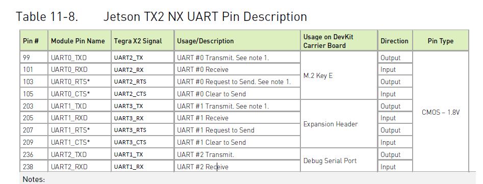
Serial 1:
PIN# | Module Pin Name
99 | UART0_TXD
101 | UART0_RXD
103 | UART0_RTS
105 | UART0_CTS

Serial 2:
PIN# | Module Pin Name
203 | UART1_TXD
205 | UART1_RXD
207 | UART1_RTS
209 | UART1_CTS

Debug UART:
PIN# | Module Pin Name
236 | (DEBUG) UART2_TXD
238 | (DEBUG) UART2_RXD

I have tried below forum topics but no change for me:

Here is dmsg log:

nvidia@nvidia-desktop:~$ dmesg |grep THS
[ 0.912907] 3110000.serial: ttyTHS1 at MMIO 0x3110000 (irq = 32, base_baud = 0) is a TEGRA_UART
[ 0.914200] 3130000.serial: ttyTHS3 at MMIO 0x3130000 (irq = 33, base_baud = 0) is a TEGRA_UART
nvidia@nvidia-desktop:~$ Connection reset by 192.168.0.7 port 22

nvidia@nvidia-desktop:~$ dmesg | grep serial
[ 0.406687] iommu: Adding device 3100000.serial to group 10
[ 0.406972] iommu: Adding device 3110000.serial to group 11
[ 0.407251] iommu: Adding device 3130000.serial to group 12
[ 0.916470] 3100000.serial: ttyS0 at MMIO 0x3100000 (irq = 31, base_baud = 25500000) is a Tegra
[ 0.938642] 3110000.serial: ttyTHS1 at MMIO 0x3110000 (irq = 32, base_baud = 0) is a TEGRA_UART
[ 0.938871] serial-tegra 3130000.serial: RX in PIO mode
[ 0.939468] 3130000.serial: ttyTHS3 at MMIO 0x3130000 (irq = 33, base_baud = 0) is a TEGRA_UART
[ 1.211971] usbcore: registered new interface driver usbserial
[ 2.266806] serial 0000:04:00.0: enabling device (0000 → 0002)
[ 2.267949] serial 0000:04:00.0: Couldn’t register serial port 0, irq 376, type 2, error -28

nvidia@nvidia-desktop:~$ dmesg | grep tty
[ 0.000000] Kernel command line: console=ttyS0,115200 root=/dev/mmcblk0p1 rw rootwait rootfstype=ext4 console=ttyS0,115200n8 console=tty0 fbcon=map:0 net.ifnames=0 isolcpus=1-2 video=tegrafb no_console_suspend=1 earlycon=uart8250,mmio32,0x3100000 nvdumper_reserved=0x1772e0000 gpt rootfs.slot_suffix= tegra_fbmem=0x800000@0x96081000 lut_mem=0x2008@0x9607e000 usbcore.old_scheme_first=1 tegraid=18.1.2.0.0 maxcpus=6 boot.slot_suffix= boot.ratchetvalues=0.2031647.1 vpr_resize bl_prof_dataptr=0x10000@0x175840000 sdhci_tegra.en_boot_part_access=1 quiet root=/dev/mmcblk0p1 rw rootwait rootfstype=ext4 console=ttyS0,115200n8 console=tty0 fbcon=map:0 net.ifnames=0 isolcpus=1-2
[ 0.000933] console [tty0] enabled
[ 0.916430] console [ttyS0] disabled
[ 0.916470] 3100000.serial: ttyS0 at MMIO 0x3100000 (irq = 31, base_baud = 25500000) is a Tegra
[ 0.935840] console [ttyS0] enabled
[ 0.938642] 3110000.serial: ttyTHS1 at MMIO 0x3110000 (irq = 32, base_baud = 0) is a TEGRA_UART
[ 0.939468] 3130000.serial: ttyTHS3 at MMIO 0x3130000 (irq = 33, base_baud = 0) is a TEGRA_UART
[ 2.267234] 0000:04:00.0: ttyS1 at MMIO 0x40300000 (irq = 376, base_baud = 7812500) is a XR17V35X
[ 2.267531] 0000:04:00.0: ttyS2 at MMIO 0x40300400 (irq = 376, base_baud = 7812500) is a XR17V35X
[ 2.267812] 0000:04:00.0: ttyS3 at MMIO 0x40300800 (irq = 376, base_baud = 7812500) is a XR17V35X

is there any changes I can make in dtbs files in source? I want RS232 and debug ports work first and the will apply my patch files for RS485/RS422.Please help

hello venkatraman.bhat,

besides device tree blob, you should also disable bpmp-dtb port and perform partition update,
i.e. $ sudo ./flash.sh -r -k bpmp-fw-dtb jetson-xavier-nx-devkit-tx2-nx mmcblk0p1
please refer to TX2 NX RS232 Communication Problem - #16 by mehmetdeniz
thanks

Hi,
I have tried thata option. did not worked for me, I will check if I miss anything.

Can I make these changes in source files? I mean in dtbs while building? I could see platform/t18x/lanai/kernel-dts/common/tegra186-p3636-0001-common.dtsi file has similar section for serial@c280000 { but not sure about how to change this in source, is this only available in bpmp-dtb form?

  • serial {
  •   port = <3>;
    
  •   has_input;
    
  • };

Hi,
I have observed 2 things,

1)I have convered dtb to dts and made changes to /Linux_for_Tegra/bootloader/tegra186-p3636-0001-p3509-0000-a01.dtb
serial@c280000 {
compatible = “nvidia,tegra186-hsuart”;
iommus = <0x11 0x20>;
reg = <0x0 0xc280000 0x0 0x40>;
reg-shift = <0x2>;
interrupts = <0x0 0x72 0x4>;
nvidia,memory-clients = <0xe>;
dmas = <0x22 0x3 0x22 0x3>;
dma-names = “rx”, “tx”;
clocks = <0x10 0xd7 0x10 0x10d>;
clock-names = “serial”, “parent”;
resets = <0x10 0x31>;
reset-names = “serial”;
status = “disabled”;
nvidia,tolerance-low-range = <0x0>;
nvidia,tolerance-high-range = <0x4>;
nvidia,adjust-baud-rates = <0x1c200 0x1c200 0x64>;
linux,phandle = <0x101>;
phandle = <0x101>;
};
to
serial@c280000 {
compatible = “nvidia,tegra186-hsuart”;
iommus = <0x11 0x20>;
reg = <0x0 0xc280000 0x0 0x40>;
reg-shift = <0x2>;
interrupts = <0x0 0x72 0x4>;
nvidia,memory-clients = <0xe>;
dmas = <0x22 0x3 0x22 0x3>;
dma-names = “rx”, “tx”;
clocks = <0x10 0xd7 0x10 0x10d>;
clock-names = “serial”, “parent”;
resets = <0x10 0x31>;
reset-names = “serial”;
status = “okay”;
nvidia,tolerance-low-range = <0x0>;
nvidia,tolerance-high-range = <0x4>;
nvidia,adjust-baud-rates = <0x1c200 0x1c200 0x64>;
linux,phandle = <0x101>;
phandle = <0x101>;
};

and then converted dts to dtb and checked again by doing dtb to dts to confirm the changes. changes can be seen. but once I flash the image and again check the dtb files by converting it to dts, I see status is reverted to disabled? any idea why?

I used below commands:
for full flash - $ sudo ./flash.sh jetson-xavier-nx-devkit-tx2-nx mmcblk0p1

any idea why its happenig like this? and if I see dmsg log after ful flash flash i get below:
nvidia@nvidia-desktop:~$ dmesg | grep THS
[ 0.935064] 3110000.serial: ttyTHS1 at MMIO 0x3110000 (irq = 32, base_baud = 0) is a TEGRA_UART
[ 0.935994] 3130000.serial: ttyTHS3 at MMIO 0x3130000 (irq = 33, base_baud = 0) is a TEGRA_UART
nvidia@nvidia-desktop:~$ Connection reset by 192.168.0.7 port 22

  1. if I try flashing only dtb and bpmp using below commands, I get flash successful but it does not boot to desktop, I see only nvidia logo

for dtb and dtb and bpmp:
$dtc -I dtb -O dts bootloader/t186ref/tegra186-bpmp-p3636-0001-a00-00.dtb > new.dts
$ dtc -I dts -O dtb -o new.tegra186-bpmp-p3636-0001-a00-00.dtb new.dts
$sudo mv new.tegra186-bpmp-p3636-0001-a00-00.dtb bootloader/t186ref/tegra186-bpmp-p3636-0001-a00-00.dtb > new.dts

$sudo ./flash.sh -r -k bpmp-fw-dtb jetson-xavier-nx-devkit-tx2-nx mmcblk0p1
$sudo ./flash.sh -r -k kernel-dtb jetson-xavier-nx-devkit-tx2-nx mmcblk0p1

Hi,
ttyTHS2 is now getting listed:

nvidia@nvidia-desktop:~$ dmesg | grep tty
[ 0.943369] 3100000.serial: ttyS0 at MMIO 0x3100000 (irq = 31, base_baud = 25500000) is a Tegra
[ 0.962732] console [ttyS0] enabled
[ 0.965251] 3110000.serial: ttyTHS1 at MMIO 0x3110000 (irq = 32, base_baud = 0) is a TEGRA_UART
[ 0.966101] c280000.serial: ttyTHS2 at MMIO 0xc280000 (irq = 33, base_baud = 0) is a TEGRA_UART
[ 0.966850] 3130000.serial: ttyTHS3 at MMIO 0x3130000 (irq = 34, base_baud = 0) is a TEGRA_UART

Now I am able to transmit between ttyTHS1 and ttyTHS2.

I am not sure why my dtb file was getting reset, I have copied the same dtb file to
/Linux_for_Tegra/kernel/dtb

Is there any chance that dtb file at /Linux_for_Tegra/bootloader/ gets replaced by dtb files at /Linux_for_Tegra/kernel/dtb ?

debug uart is still not working for me, any suggestion? do I need to change base baud? if so how?

hello venkatraman.bhat,

it’s the path, $OUT/Linux_for_Tegra/kernel/dtb/ for the flash script to load the device tree blob.
please check the flash.sh for the details.
for example,

LDK_DIR=$(cd `dirname $0` && pwd);
...
KERNEL_DIR="${LDK_DIR}/kernel";
DTB_DIR="${KERNEL_DIR}/dtb";

it’s the flash script to copy the dtb file to bootloader folder,
for example,

if [ "${dtbfile}" != "" ]; then
        cp2local dtbfile "${BL_DIR}/${dtbfilename}";
1 Like

hello venkatraman.bhat,

did you mean UART2_TX/RX?
it’s uartb: serial@3110000, which mapping to ttyTHS1.

[EDIT]
that’s right, it’s a 6-pin UART header on the developer kit carrier board.
form the software side it uses uarta: serial@3100000

Where can I get this mapping?

Below are not for debug console?
236 | (DEBUG) UART2_TXD
238 | (DEBUG) UART2_RXD

I thought these pins are mapped to ttyS0 serial@3100000 debug UART. What are the pins for console [ttyS0] serial@3100000 ?

please refer to Topic 153941, it shows the mappings for serial ports of ttyTHS*, and UART*

Hi I went through the post,

I see with the source/public/hardware/nvidia/soc/t18x/kernel-dts/tegra186-soc/tegra186-soc-uart.dtsi.dtsi and TX2 NX Pinmux files. Also referred product design guide. I am bit confused here.

debug serial port is serial@3100000 :ttyS0 236 UART2_TXD 238 (DEBUG),UART2_RXD (DEBUG) , is that correct? I have connected the serial to USB adaptor to these pins and it is not working for me

uarta: serial@3100000 :ttyS0 236 UART2_TXD 238 (DEBUG),UART2_RXD (DEBUG)
uartb: serial@3110000 :ttyTHS1 99 UART0_TXD 101 UART0_RXD
uartc: serial@c280000 :ttyTHS3 203 UART1_TXD 205 UART1_RXD

uarta: serial@3100000 {
compatible = “nvidia,tegra186-hsuart”;
iommus = <&smmu TEGRA_SID_GPCDMA_0>;
reg = <0x0 0x03100000 0x0 0x40>;
reg-shift = <2>;
interrupts = <0 TEGRA186_IRQ_UARTA 0x04>;
nvidia,memory-clients = <14>;
dmas = <&gpcdma 8>, <&gpcdma 8>;
dma-names = “rx”, “tx”;
clocks = <&tegra_car TEGRA186_CLK_UARTA>,
<&tegra_car TEGRA186_CLK_PLLP_OUT0>;
clock-names = “serial”, “parent”;
resets = <&tegra_car TEGRA186_RESET_UARTA>;
reset-names = “serial”;
status = “disabled”;
nvidia,tolerance-low-range = <0>;
nvidia,tolerance-high-range = <4>;
nvidia,adjust-baud-rates = <115200 115200 100>;
};

uartb: serial@3110000 {
	compatible = "nvidia,tegra186-hsuart";
	iommus = <&smmu TEGRA_SID_GPCDMA_0>;
	reg = <0x0 0x03110000 0x0 0x40>;
	reg-shift = <2>;
	interrupts = <0 TEGRA186_IRQ_UARTB 0x04>;
	nvidia,memory-clients = <14>;
	dmas = <&gpcdma 9>, <&gpcdma 9>;
	dma-names = "rx", "tx";
	clocks = <&tegra_car TEGRA186_CLK_UARTB>,
		<&tegra_car TEGRA186_CLK_PLLP_OUT0>;
	clock-names = "serial", "parent";
	resets = <&tegra_car TEGRA186_RESET_UARTB>;
	reset-names = "serial";
	status = "disabled";
	nvidia,tolerance-low-range = <0>;
	nvidia,tolerance-high-range = <4>;
	nvidia,adjust-baud-rates = <115200 115200 100>;
};

uartc: serial@c280000 {
	compatible = "nvidia,tegra186-hsuart";
	iommus = <&smmu TEGRA_SID_GPCDMA_0>;
	reg = <0x0 0xc280000 0x0 0x40>;
	reg-shift = <2>;
	interrupts = <0 TEGRA186_IRQ_UARTC 0x04>;
	nvidia,memory-clients = <14>;
	dmas = <&gpcdma 3>, <&gpcdma 3>;
	dma-names = "rx", "tx";
	clocks = <&tegra_car TEGRA186_CLK_UARTC>,
		<&tegra_car TEGRA186_CLK_PLLP_OUT0>;
	clock-names = "serial", "parent";
	resets = <&tegra_car TEGRA186_RESET_UARTC>;
	reset-names = "serial";
	/*status = "disabled";*/ /*testing*/
	status = "okay";
	nvidia,tolerance-low-range = <0>;
	nvidia,tolerance-high-range = <4>;
	nvidia,adjust-baud-rates = <115200 115200 100>;
};


UARTA_TX2NX
UARTB_TX2NX
UARTC_TX2NX
tegra186-soc-uart.dtsi (5.3 KB)

these combinations are working for me , Like if I try using minicom and connect serial cable to these pins I am able to tx/rx data.

But debug pin combination I tried to connect
236 | (DEBUG) UART2_TXD
238 | (DEBUG) UART2_RXD
to a serial to USB and used teraterm in a host machine, I get no boot console, not able to use serial console. But with same carrier board and pin config I am able to connect via serial console in Nano.

hello venkatraman.bhat,

that’s right, I’ve revise my previous comments for the UART mappings also.
could you please check Jetson TX2 NX Product Design Guide for the [Debug UART Connections].
please check the footnote, please check whether you had level shifter implemented.
thanks

1 Like

I have checked, we have a level shifter
image
image

I see some junk characters on the console for all the Baud rates (I know Console Baud should be 115200, just checked with other BRs). My connections are correct as same Debug port works for Nano and NX modules on the same carrier Board.

Are some characters correct at any given baud rate on the console? If so, then I would suspect noise. How long are your RX/TX cables? Are they shielded? You might try two things:

  • Loopback, where the cable is the full length sitting as close as possible to the route it would take, but RX and TX shorted. See if echo of content has partial correct versus partial corrupt content.
  • In the current setup, see if the corrupt characters correspond to a particular input, or if it is random (see if repeating the same input results in the same or different corruption).
  • Try with the shortest possible cable. Make sure it uses quality twisted pair and is shielded. Good ethernet cable is what I tend to use.

All the characters are corrupt. Cable length is not more than 1 meter and it is shielded cable.

I have tried the shorter cable as well. I will check the other options suggested

Since all characters are corrupt, then I’d suspect either noise/signal quality issues, or else settings related to stop bits or (in the case of terminals which interpret character sets) language settings.

Note that character sets are not an issue with loopback, so loopback testing is important. Noise and signal quality are also not generally an issue with loopback when the cable is short or the loopback jumper itself is directly on the Jetson (the ultimate of short cables). If loopback succeeds independently on both host side and client side, or if loopback fails, then you’ve completed some very important and informative testing.

If loopback works on both ends, but connection across units fails, then you know corruption is probably either noise related or stop bit settings or character set related. One way to look at incorrect stop bits is to send a constant pattern and look at the result in hex instead of looking at it as a character, thus eliminating any character encoding issues; then see if there is a pattern of a bit missing or being added that you didn’t know about…the hex would basically be a shift of some subset of the pattern.

1 Like

I am able to see characters getting echoed if TX and RX shorted. But if I connected any serial to USB cable I am getting junk characters. tried with different cables.

But with these cables It perfectly works with Nano/Nx

Does your serial USB cable also have the ability to echo characters without corruption when in loopback mode? The side you tested can be guaranteed as correct function since loopback worked. If the side with USB can be used with loopback, then the same can be said of that.

In the case where two devices which work in loopback succeed, but fail when working together, then you have one of these issues:

  • One end has different settings than the other. For example, number of bits or number of stop bits, maybe even speed.
  • There is noise or signal loss, e.g., cable too long, not twisted pair, unshielded to make it worse.
  • Each end may be operating at a different voltage. Jetsons use a 3.3V TTL level UART. Is the USB cable 3.3V?

Hey I have missed to comment on that, USB cable also fine if I loopback between TX- RX pins of the cable.

yes it is 3.3 V, Also it worked fine with Nano/NX modules on same carrier board… this is what is making me to not understand the issue