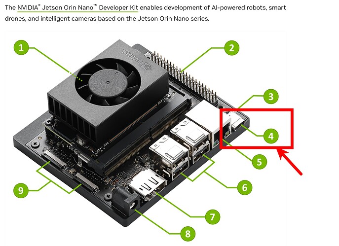
[R35.4.1] Flash SPE FW for Orin nano FAILED, always stuck at "tegrarcm_v2 --chip 0x23 0 --ismb2applet"

,

Hi, I got a problem on flash a spe fw to orin nano. Linux_for_Tegra version is R35.4.1

  1. compile the spe fw ok, copy the spe fw to bootloader and renamed fw ok.
  2. after command: “sudo ./flash.sh -k A_spe-fw jetson-orin-nano-devkit nvme0n1” , script running .
  3. but finnaly, it stuck at a line blew. Even try the original fw which comes with l4t, It could not flash the spe fw to the orin nano successfully.

[ 43.4442 ] tegrarcm_v2 --chip 0x23 0 --ismb2applet
[ 1053.6669 ] tegrarcm_v2 --chip 0x23 0 --ismb2

I suspect this is an official question, since I see that the document background image is a draft marker. Jetson Sensor Processing Engine (SPE) Developer Guide: Compiling and Flashing

SCREENSHOOT:

FLASH_LOG:
flash_spe_fw_mmcblk0p1.txt (70.0 KB)

Do not know why, Did anyone see this,please help me. THANKS!!

Hello,
Have you ever changed anything in SPE firmware.
My suggestion is to start from original SPE firmware, without any change, and confirms the full process is good.

SPE firmware crash may hang the flash process.

br
Chenjian

Sadly, even I try the FW which comes with nvidia official l4t in the bootloader/spe_t234.bin, It could not flash the spe fw to the orin nano successfully.

sudo ./flash.sh -k A_spe-fw jetson-orin-nano-devkit mmcblk0p1

CHANGE NOTHING FOR SEP FW, but It cames with the same issue.

@jachen, Just use NVIDIA’s built-in SPE firmware for burning. Have you tried my operation yet?

Hello,

  1. Please try following initrd flash command first.
    sudo ./tools/kernel_flash/l4t_initrd_flash.sh --external-device nvme0n1p1 -c tools/kernel_flash/flash_l4t_external.xml -p “-c bootloader/t186ref/cfg/flash_t234_qspi.xml” --showlogs --network usb0 jetson-orin-nano-devkit-nvme internal

  2. With flash command, can you share the UART log from device side? So we can know where the device hangs.

br
ChenJian

Hi @jachen
Q1. with the flash command :

sudo ./tools/kernel_flash/l4t_initrd_flash.sh --external-device nvme0n1p1 -c tools/kernel_flash/flash_l4t_external.xml -p “-c bootloader/t186ref/cfg/flash_t234_qspi.xml” --showlogs --network usb0 jetson-orin-nano-devkit-nvme internal

the device will not be flashed, UART log form device:

*** no-flash flag enabled. Exiting now… ***

User can run above saved command in factory environment without
providing pkc and sbk keys to flash a device

Example:

$ cd bootloader 
$ sudo bash ./flashcmd.txt

Save initrd flashing command parameters to /home/hengyongchao/NVIDIA/R35.4.1/DRIVERS/Linux_for_Tegra/tools/kernel_flash/initrdflashparam.txt
/tmp/tmp.6wbGQ1QwIp /home/hengyongchao/NVIDIA/R35.4.1/DRIVERS/Linux_for_Tegra
writing boot image config in bootimg.cfg
extracting kernel in zImage
extracting ramdisk in initrd.img
/tmp/tmp.6wbGQ1QwIp/initrd /tmp/tmp.6wbGQ1QwIp /home/hengyongchao/NVIDIA/R35.4.1/DRIVERS/Linux_for_Tegra
58247 blocks
84463 blocks
/tmp/tmp.6wbGQ1QwIp /home/hengyongchao/NVIDIA/R35.4.1/DRIVERS/Linux_for_Tegra
flashimg0=boot0.img
/home/hengyongchao/NVIDIA/R35.4.1/DRIVERS/Linux_for_Tegra
Success
Cleaning up…
Finish generating flash package.
No devices to flash

Here is the full logs: paramwter-with-nvme-full-log-1.txt (241.1 KB)


But if I chanage it to flash command which the parameter “jetson-orin-nano-devkit” different with “jetson-orin-nano-devkit-nvme” :

sudo ./tools/kernel_flash/l4t_initrd_flash.sh --external-device nvme0n1p1
-c tools/kernel_flash/flash_l4t_external.xml -p “-c bootloader/t186ref/cfg/flash_t234_qspi.xml”
–showlogs --network usb0 jetson-orin-nano-devkit internal

The device will flash successed, full log here
parameter_no_nvme-flash-full-log-2.txt (286.4 KB)

writing item=16, 9:0:secondary_gpt, 62545444352, 16896, gpt_secondary_9_0.bin, 16896, fixed--0, 01977158d8da3fef855d093d25bd01eea111360f
[ 226]: l4t_flash_from_kernel: Successfully flash the external device
[ 226]: l4t_flash_from_kernel: Flashing success
[ 226]: l4t_flash_from_kernel: The device size indicated in the partition layout xml is smaller than the actual size. This utility will try to fix the GPT.
Flash is successful
Reboot device
Cleaning up…
Log is saved to Linux_for_Tegra/initrdlog/flash_3-2.1.2_0_20230823-163228.log


Q2: logs atched above the text.


Whatever jetson orin nano restart or enter recovery mode, PSE and CCPLEX do not print anything. It seems SPE FW never working, but I saw the “disable_spe = 0” macro was set to 0. The PSE R5 should works and print something.

And also confused with the commmands:

  1. sudo ./flash.sh -k A_spe-fw jetson-orin-nano-devkit mmcblk0p1
  2. sudo ./flash.sh -k A_spe-fw jetson-orin-nano-devkit-nvme mmcblk0p1

Jetson Modules and Configurations do not has the jetson-orin-nano-devkit-nvme Configuration, why are you suggest use the jetson-orin-nano-devkit-nvme parameter for flash.sh script.

Hi @jachen

UPDATE:

  1. After flash commmand, I update the whole system:

  1. Then I use the flash command to update the spe fw successfully.

sudo ./flash.sh -k A_spe-fw jetson-orin-nano-devkit-nvme mmcblk0p1

Flash SPE FW, use command “sudo ./flash.sh -k A_spe-fw jetson-orin-nano-devkit-nvme mmcblk0p1” will be ok. But use “sudo ./flash.sh -k A_spe-fw jetson-orin-nano-devkit mmcblk0p1” will get failed.

Confused me, when flash the whole image, dot not use “jetson-orin-nano-devkit-nvme”, must use “jetson-orin-nano-devkit” parameter, if so that will get failed. That’s odd!


  1. But still not set any print log form SPE terimal. I do add some print in the spe source code., Please help me to check why spe not print logs.

Hello,
You can capture the full UART log directly (minicom), without jetson_demux, first.
From your snapshot, it seems that nothing printed in console. The device does not boot up correctly?

What’s the change you made?
You can just compile the original SPE firmware, and in console, you should see following logs:

I> Unhalting SPE…
I> Enabling combined UART
����init uartc for combined uart
��

And init uartc for combined uart comes from SPE firmware.

br
ChenJian

Hi @jachen

should I connected which TX,RX gpio in the orin nano? Or just connect the orin nano debug port?

With minicom connect to the usb-c, can not see the logs that you show above. Here is mine.

Hello,
usb-c is not the debug port. That’s a USB composite gadget device when device’s up.
For debug UART port, please take a look at Jetson Nano & NX Style - Serial Debug Console - JetsonHacks
and picture https://jetsonhacks.com/wp-content/uploads/2020/04/IMG_3615Small.jpg.webp shows the correct connection of debug UART TX/RX pin (green/white), also please connect the ground pin. You may need an extra USB-UART adaptor.

br
ChenJian

1 Like

Hi @jachen

Thanks for your helps. I have successfully modify and update the spe fw in orin nano now.


But I have another question:

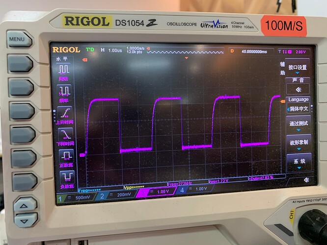
I am testing the level flip of GPIO in gpio app tak, the current maximum speed is 270Khz. This can’t meet my needs, I need about 1Mhz toggle frequency to simulate some LED(rgb) driving signal. I noticed that the maximum frequency of the R5 processor is about 200Mhz, want to know what is the maximum flipping speed of the GPIO of the R5 processor?


In other words, how to realize LED driving on orin nano? I tried PWM, but currently I have no way to realize a single variable duty cycle pwm pulse output on orin nano. It is used to simulate the output of 0 code and 1 code, that is, only one cycle waveform is output at a time, similar to the driving method of a stepping motor.

Thanks!

Hello,
Though I’ve not tested, but your test result should be reasonable. If GPIO is toggled by software (SPE firmware), the max frequency should be unlikely to reach so high, like 1MHz.

Let’s go back to PWM. If using PWM, do you still need that port of control stay in SPE, or CCPLEX (Linux) is good?
For SPE, only PWM4 is available. And CCPLEX may have more options.

br
ChenJian

Hi @jachen

Does SPE in orin nano has pwm4 to use? I did not see it in the spe document.

Hello,
You are right. Unfortunately, there’s no PWM sample code supported in current SPE firmware package.

So my suggestion is that to move PWM to CCPLX (Linux) side, which may be easy to handle.

br
ChenJian

Hi @jachen

If we can use pwm to output a waveform with a variable duty cycle and a fixed frequency of 500khz or 1mhz under CCPLX (Linux) side, my problem can be solved. But the current jetson-gpio api has no way to output a single pwm waveform, which is the key problem.

image

The pwm output of jetson-gpio is continuous and cannot be precisely controlled to output several waveforms individually.

Hello,
My point is to use PWM directly, instead of GPIO simulation.

Does that help?

br
ChenJian

Hi @jachen

Yes, totally agree. I also don’t like the bit-bang in that high frequency.

I tried pwm before. However, the problem encountered is that how to use pwm to construct single-bus data code 0 and code 1.

Hi @jachen

So, the question sums up as: How to use jetson orin nano to output a waveform, with adjustable pwm duty cycle, with fixed pwm frequency? a pulse output like stepper motor control plus.

If it can be achieved, then my problem is completely solved.

Thanks so much!

Hello,
For PWM, you can take a look at PWM pin in fan jacket, together with the driver in kernel for reference. (Orin Nano devkit)
PWM should not be so difficult per my understanding. TRM chapter PWM may also help.

br
ChenJian

Hi @jachen

If it is not difficult for you to use orin nano to output a pwm waveform (non-periodic output), this is definitely good news for me!

I used the orin nano’s pwm output to drive the buzzer to play music and it worked fine with no issues. But there is really no way for me to make pwm output an independent waveform (non-periodic output) in CCPLX (Linux) side.

Please help me, Please give me an example that pwm output a square wave (non-periodic output) with a duty cycle of 14% and a frequency of 500khz, just one signal wave. Thank you very much!

@jachen

Since this discuss seems to have strayed from what the title named, I’ll start a new thread discussing it.