Please check if you understand this comment or not. Because from your dts, I don’t think you realiezed it.
You need to give a always-on regulator which is also 3.3v to the vmmc-supply. It cannot be just random dummy regulator
Please check if you understand this comment or not. Because from your dts, I don’t think you realiezed it.
You need to give a always-on regulator which is also 3.3v to the vmmc-supply. It cannot be just random dummy regulator
sorry, I don’t quite understand how to set vmmc-supply,I refer to some other people’s methods,
tegra194-power-tree-p3668.dtsi
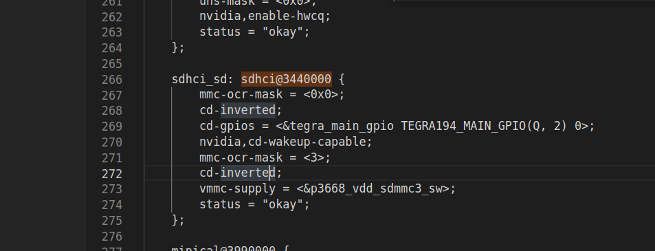
sdhci@3440000{
vmmc-supply = <&p3668_spmic_ldo3>;
vmmc-supply = <&p3668_spmic_sd2>;
}
The 3V3 of SD on my hardware is always provided stably
你可以先看一下你設定的"battery_reg"的電壓是給多少
然後再看一下我講的那句話.
You could firstly check what is the voltage of that “battery_reg” regulator. And then read my comment again. You shall know what I am talking about.
這個也可以刪掉了
nvidia,vqmmc-always-on;
you can also remove this.
Also, these are all the sdmmc3 issue on NX forum. Please take a look.
https://forums.developer.nvidia.com/search?q=sdmmc3%20%23jetson-embedded-systems%3Ajetson-xavier-nx

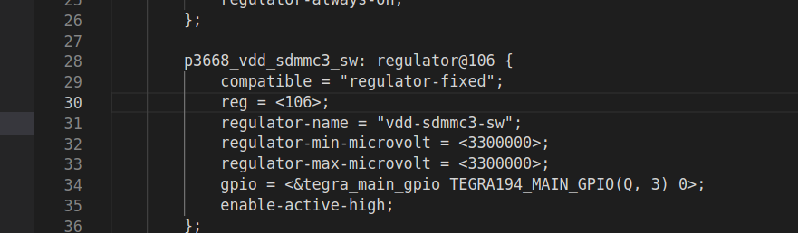
hello, why vdd-sdmmc3-sw will be disabling
If that regulator is not in use, then it is normal it will be disabled.
dmesg.txt (49.2 KB)
請問一下你到底現在要用哪一種底板做測試?
不用換來換去, 要用有gpio的底板就麻煩貼上有gpio的線路圖. 有gpio跟沒有gpio控制的device tree寫法是不一樣的
如果regulator最後被關掉, 代表說你這個regulator在整個過程中都沒有被用上. 沒有被用上的原因有很多種, 比方說你根本卡沒插, 或是你sdmmc3根本沒開.
Could you clarify what kind of carrier board you want to use now? Please just stick to one kind of board. If you want to use a board with gpio to control, then you need to attach the schematic of that kind. The device tree will be different when different board is in use.
If the regulator is off in the end, it means this regulator is not in use at all. The reasons behind “not in use” could be varied. For example, the card is not plugged at all or even sdmmc3 is not ON.
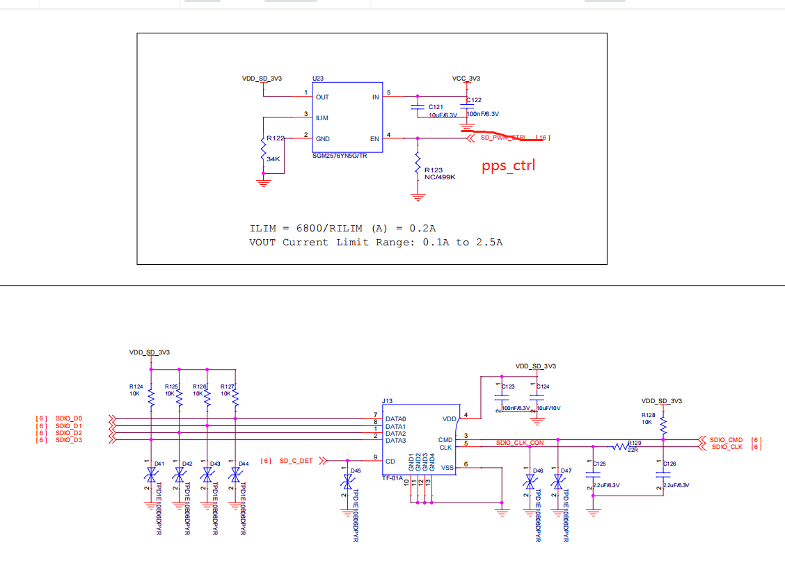
I’m sorry, because I tried the method without gpio control and it didn’t work, and I referred to other articles on the forum with gpio control, so I changed it back and attached the schematic diagram
the pps_ctrl is gpio control, thank you

可以請你去量一下實際上開機跑起來之後到底有沒有3.3v的VDD嗎?
Can you measure whether there is a 3.3v VDD after actually starting up and running?
hello, i measure the 3V3 VDD, the gpio control borad is not 3v3 VDD, i will communicate with hardware engineers.
But i dont know, why is there no 3V3, the kernel will still print the information of the sd card, although it will not run successfully in the end, thank you very much
你可以確認一下你的cd-gpio 那些到底有沒有設對
比方說你沒插卡的時候是不是還會印sd log.
You can firstly check if those cd-gpio is correctly set or not. For example, whether there is still sd log even when you don’t have any card insertion…
cd-gpio is right,There is an error message when I hot-plug
I measured the voltage and found that according to my settings above, the gpio control does not have a high level output after power-on, resulting in no voltage on the sd 3v3. Is this a problem with my device tree settings? My cd-gpio is GPIO8, control -gpio is GPIO2,
thanks
你可以確認一下GPIO2的pinmux 設定有沒有對
You can check whether the pinmux of that GPIO2 is correct or not.
Hello, I modified the device tree referring to the table, is this correct?
![]()
其實與其給我看pinmux spreadsheet其中一欄截圖, 你應該要講一下你怎樣更新後續的東西…
比方說這個excel會產生3個dtsi檔案, 你後續如何拿這些東西去更新你的pinmux? 這些資訊比你現在貼的東西有意義…
另外, 插拔sd卡的時候, 這根gpio有沒有被toggle?
CMD CRC 這種錯誤通常都是硬體問題…而且使用GPIO控制VDD的底板其實是增加多一個變因. 所以我才會一開始建議你就直接用沒有gpio控制的底板確認你其他功能是正常還是不正常…
我不知道你為何又要換底板. 這件事情其實只是徒增問題點而已.
Rather than sharing a column from pinmux spreadsheet, you should tell us how you updated the later stuff…
For example, this excel woud genearte 3 dtsi files and how did you update pinmux with these files? This info would be more helpful than what you just posting…
Also, check gpio is being toggled or not when inserting sdcard.
CMD CRC error generally comes from wrong hardware. And you are creating one more variable when you use a board which has gpio to control the VDD…
That was why I suggested you to use the always-on power source carrier board first.
I am not modifying the gpio through the dtsi generated by the table, I am directly modifying the dtsi.
Oh well, I should still use the one without the GPIO control, right? I just read the recommended manual and other people on the forum use it so I thought maybe this would solve my problem better.
Is there any level change in gpio-control when inserting and unplugging SD card?
Thank you