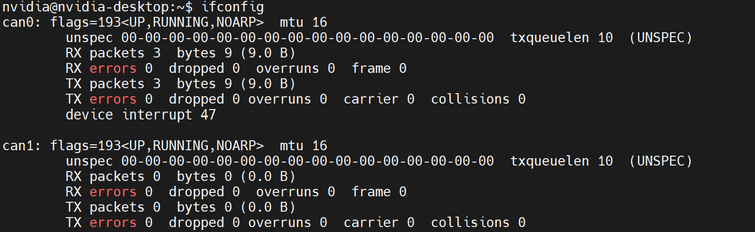
I am configuring mcp2515 on R35.1 and restarting the development board after completion. Using the ifconfig command, I can see the configured can1. However, during loopback testing, I used cansend to send data, but candump did not receive it.What are the solutions available,thank you!
Hi Yolomei,
Are you using the devkit or custom board ?
Could you help to verify with latest JP5.1.1(R35.3.1)?
May I know why you don’t just use J17 for CAN Bus as following?

Could you also share the commands you used to setup CAN transmission?
Do you use CAN transceiver for loopback test?
- I need two CAN channels, but NX only has one channel;
- The R35.3.1 version also has the same issue;
- I am using a custom board. Running R32.7.1 with the same configuration is no problem
sudo modprobe mcp251x
sudo ip link set can1 type can bitrate 500000 loopback on
sudo ip link set up can1
The device tree is configured as
tegra194-p3668-0001-p3509-0000.dts (1.8 KB)
Have you configured and verified SPI work in R35.3.1?
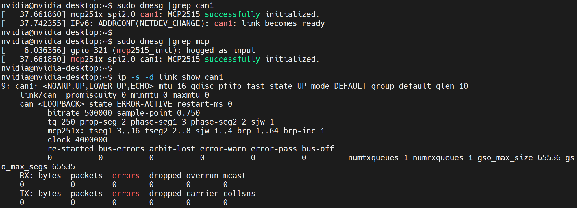
Could you also share the dmesg for further check?
Could you help to compare if the pinmux for SPI different between R32.7.1 and R35.3.1?
dmesg.c (67.9 KB)
Can I confirm with you if the current issue happen on MCP2515 ony?
(i.e. Does the J17 Can bus work as expected currently?)
Please run the following command for both R32.7.1 and R35.3.1 to check pinmux for SPI.
sudo busybox devmem 0x0243d060 //SPI3_MOSI
sudo busybox devmem 0x0243d008 //SPI3_MISO
sudo busybox devmem 0x0243d048 //SPI3_SCK
sudo busybox devmem 0x0243d018 //SPI3_CS0
sudo busybox devmem 0x0243d028 //SPI3_CS1
Yes, the J17 can bus is working normally.
The pinmux values for both versions are consistent, as shown below
0x0243d060 0x1404
0x0243d008 0x1454
0x0243d048 0x1404
0x0243d018 0x1404
0x0243d028 0x1404
The pinmux values of GPIO12 connected to pin INT of mcp2515 chip are all 0x5a
Hello, after comparing the interrupt allocation between the two versions, there are some differences: in R32.7.1, mcp251x was assigned an interrupt; In R35.1, spi2.0 has been assigned interrupts, which are theoretically the same program, but do you know if there is a difference?
r32.7.1-interrupts.c (16.8 KB)
r35.1-interrupts.c (10.2 KB)
I would still suggest using R35.3.1 to do further debug to prevent that we are look into some issues which have been resolved.
Could you provide the device trees for both R32.7.1 and R35.3.1?
Okay, I have switched to R35.3.1;
The device trees set in R35.3.1 and R32.7.1 are consistent with the published ones above
Do you have the same interrupt configuration for mcp2525 on both R32.7.1 and R35.3.1?
What do you mean about the “published ones above”?
There should be some differences of the device tree for these two Jetpack version.
Above is the device tree I posted.
The configuration of mcp251x is the same in each version because their addresses are the same
I found can0 is the default can bus, which come with internal loopback and could be verified with the steps from the developer guide.
can1 is from mcp2515, how do you verify it with loopback test?
Could you share any block diagram of your connections and every command you used to setup can1 and transmission?
In the above reply, first load the driver and set the loopback.
The ‘candump can1’ command receives data,and the ‘cansend can1 123#1234’ command sends data. However, candump cannot receive data
There is no update from you for a period, assuming this is not an issue any more.
Hence we are closing this topic. If need further support, please open a new one.
Thanks
How did you connect CAN1 TX and RX for loopback test?
Have you tried to use 2 CAN transceivers and connect as the instruction to transmit data from can0 to can1?