@juha.kauppi I haven’t worked with that specific hat, but waveshare used to sell one based on the mcp2517fd. Seeedstudio sells a 2 channel mcp2518fd based can hat and they also have an excellent driver for the nano, which also happens to work with the waveshare mcp2517fd hat. I suggest switching to the seeedstudio canfd hat if you can. The driver builds and installs and just works. I have two of them and they work perfectly with both the nano and raspi. Or use the waveshare canfd hat if you can find one, with the seedstudio driver.
CANFD is the latest version of the CAN spec. It is much faster and supports larger packets. However the mcp251xfd chips from microchip are fully backward compatible, so if you actually need classic can, these will work nicely there too.
I am also having same issue. I created new thread so I will link it here for others Jetson Nano and SPI CAN Bus - #7 by oxoocoffee
Is there anyone in recent times who was able to get one CAN bus working?
I was able to get the canbus working. I deviated from the guide here as I was having issues with the tegra210-p3448-0000-p3449-0000-b00-mcp251x.dtbo that @shgarg posted. I had similar issues to the guys above with the unit not booting up on the B00 variant.
I found that seeed studio posted on git its overlay for their CAN hats for the jetson-nano. I modified it to work with a CAN hat that uses the mcp251x chip discussed in this thread, but you could use their can hat and drivers as is.
I changed all instances of mcp2518fd to mcp2515.
I also removed all the can1 info/setup since the CAN hat I am using only has one CAN chip on it.
I’ve included my dts file for reference. If you use this file copy it to the overlays/overlays/jetsonnano folder.
Run make all_jetsonnano.
Copy the generated MCP251x.dtbo to /boot.
Once copied over run “sudo /opt/nvidia/jetson-io/jetson-io.py” and configure the Jetson for compatible hardware and select the CAN module you just added.
Doing it this way you don’t need to modify the tegra210-p3448-0000-p3449-0000-b00-mcp251x.dtbo file.
Thank you for your information.
Following your advice, I successed “jetson-io.py” process and I was able to confirm can0 had enabled on my JetsonNano.
After that I connected an another can device to Can Bus for trial
and to try to send data from the another device to my JetsonNANO.
Unfortunately, I could not receive data by “candump can0”.
The mcp2515 chip that I use may be out of order.
Or I probably mistook or lacked proseadure.
I will check them.
Thank you for sharing the information.
I downloaded your MCP251x.dts.txt file and After I applied your step, I couldn’t run jetson-io.py. After running the command. I see a flash of grey. It is probably launched and closed immediately. So I used 2xMCP2518FD-spi0.dtbo and I could execute jetson-io.py. It works until this step.
Can you guide me on how to confirm that mcp2515 is working? I don’t have much information coding CanBus
I then found the cause of the CAN communication failure.
I connected the wrong pin on my JetsonNANO.
The “INT” pin on MPC2515 have to connect to pin No.22 on NANO.
This was noted on line no.63 and 82-88 of MCP251x.dts.txt that andrew_h shared.
MCP2515 have been working on NANO. The CAN data sending and recieving became enable.
I have a peak-usb that I connected to the MCP2515 Low and High pin, USB side connected to my laptop(I will see receive message with pcanview). But I don’t have knowledge about how to send messages with MCP2515.
Could you guide me about how to send messages using python or through the terminal? How to test MCP2515 is working for me?
But I can’t send messages through the PCAN-USB to my laptop. My connections are between MCP2515 and PCAN-USB are: LOW-Pin2 , HIGH-Pin7. I am trying to see the received message using the pcanview. I don’t get an error while sending a message from jetson but I can’t view it on pcanview. Is there a problem until here?
Also I found this blog and It says you need to modify MCP2515
Because MCP2515 must be powered from 3,3V, because MCP2515 is directly connected to Pi GPIO and GPIO only accept 3,3V , higher voltage will break pin (so powering MCP2515 and TJA1050 from 5V will break Pi IOs). The TJA1050/MCP2551/etc. CAN bus transceiver must be powered from 5V, because CAN bus operates on 0V and 5V levels, lower high level is considered as noise/distortion (this is defined by CAN Bus specification).
Did you modify your MCP2515 like this?
My connections are:
MCP2515 Jetson
INT pin 22
SCK pin 23
SI pin 19
SO pin 21
CS pin 24
GND GND
VCC 3.3V
Dear tnakyol,
I modified my mcp2515 board because TJA1050 need 5V for power.
I assigned 3.3V to the power for MCP2515 and 5V to TJA1050.
I used No.2 pin of JetsonNANO’s GPIO to input 5V to TJA1050.
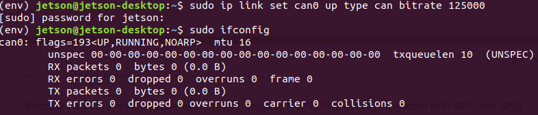
I saw your response view of “ifconfig”.
It seems MCP2515 is working well.
Did you try the “cansend” command?
You may also need to replace the MCP251x.ko driver as one of the members has said above to enable gpio interrupts. I rebuilt the driver myself adding in his patch. His may work just as well. I have also seen responses where this is not needed but modifying it did get it working for me. Building the driver for myself I was able to find that I was missing the &gpio in my overlay as the of_get_named_gpio() function was not finding the pin specified until I added that in.
I have attached the modified driver as well. mcp251x.ko.txt (500.9 KB)
If the interrupt pin is configured correctly you should be able to receive data. At this point I still had issues with one of my MCP251x and would get two errors for every packet received, and if I tried to transmit the canbus would go to the BUS-OFF state.
A sidenote here is even if you have the IRQ pinned out wrong, wrong pin selected on the Jetson nano or connected incorrectly from the MCP251x device to the Jetson nano, the MCP251x driver can still initialize and not work.
I believe the difference here was that the 2 CH CAN HAT has a 3.3v/5v logic select jumper set to 3.3v. I do have the MCP2515 that @tuna.akyol has and will try that mod and see if it works.
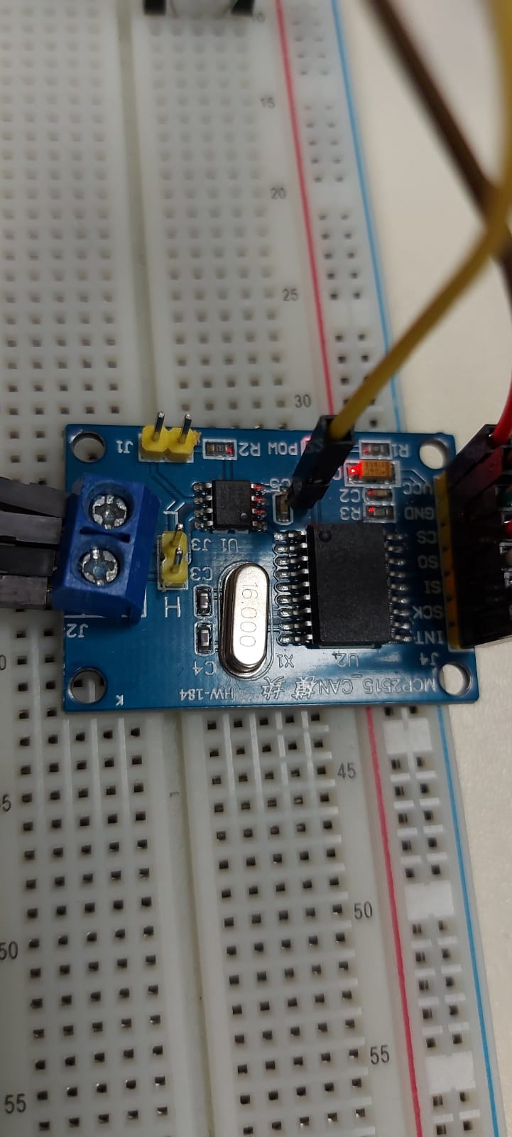
Yes you need to change the clock-frequency = <8000000> to clock-frequency = <16000000>. It should match the crystal on the board and from your picture it shows a 16MHz crystal.
You can skip step 2 here and just copy the MCP251x.dtbo.
I modified my board as well and everything is working as it should. On your mod make sure you cut the trace connecting C5 to the 3V rail. If you don’t you are bridging the 3v and 5v rails.
I cut mine right between the via and the capacitor
.
Other than that the only other difference is that my board has a 8MHz crystal and switched to spi0.cs1 (pin26).
For some reason spi0.cs0 causes RX errors and when I try to transmit the bus turns off.
Hey tuna.akyol
I used jetpack 4.3 so im not sure of there step I Will give you now Will work but here they are.
What I did was.
Started with a new fresh image(jetpack 4.3 or 4.4)
Downloaded the The sources make sure it’s for the same jetpack version
Find the mcp251x.c driver somewhere in the sources you just downloaded and add what shgarg gave us in a txt file above somewhere
Build the kernel sources and there Will be generated a new mcp251x.ko file
The new generated ko file should replace the Old one I Think it was Under lib/… net/can shgarg wrote it somewhere above
Copy the dtb file shgarg gave us above to /boot/dtb and the dtbo to /boot
Run Jetson-io.py and enable spi
Reboot and try dmesg | grep mcp
Sorry If some steps are wrong but as far I remember it was there steps I followed and I was able to read and send with can1 and sometimes with can0. I stopped working with the project and dont have a Jetson anymore im sorry
I know this thread is really Big and Maybe confusion. Im not sure if you can use there steps with the newest version of jetpack
Hi All ,
Jetpack 4.5 released and I just change can clock according mine mcp2515 clock freq follow steps on bellow. Evrything looks ok but stil no comunication .
Run /opt/nvidia/jetson-io/jetson-io.py
Select Configure Jetson for compatible hardware
Select MCP251x CAN Controller
Save and reboot
Make CAN0 and CAN1 inerface up on network:
ip link set can0 up type can bitrate 125000 loopback on
ip link set can1 up type can bitrate 125000 loopback on