LIC interrupts and GPIO controllers

Hello.

We have asked the same question in two different threads and would like to have a technical expert to answer it. The questions are in these two threads:

The issue is reproducible with the latest Jetpack (Linux for Tegra) on the devkit, so the issue is not in the custom board. I can provide details on how to reproduce if need be.

Thank you.

Hi antti.keranen,

It seems you and @HannuHHH from the same company.
We are checking the interrupt behavior with internal, and will let you know once there’s any result.

Yes, please help to provide your reproduce steps of using interrupt pins on the devkit.

All right, these are the steps to reproduce:

Device setup

Download Jetson Linux R35.3.1 and the sample root filesystem from the download page.
Extract with:

sudo tar xpf ./Jetson_Linux_R35.3.1_aarch64.tbz2
sudo tar xpf ./Tegra_Linux_Sample-Root-Filesystem_R35.3.1_aarch64.tbz2 -C Linux_for_Tegra/rootfs

Take gpiotest.dtbo into use

cp gpiotest.dtbo Linux_for_Tegra/kernel/dtb/gpiotest.dtbo
sed -ie 's/OVERLAY.*/OVERLAY_DTB_FILE=gpiotest.dtbo/' Linux_for_Tegra/jetson-agx-xavier-devkit.conf

Set Port Z Pin 4 to INT1

sed -ie 's/Z.pin.4 = 0/Z.pin.4 = 1/' Linux_for_Tegra/bootloader/t186ref/BCT/tegra194-mb1-bct-gpioint-p2888-0000-p2822-0000.cfg

Flash

cd Linux_for_Tegra
sudo ./apply_binaries.sh
sudo ./flash.sh jetson-agx-xavier-devkit mmcblk0p1

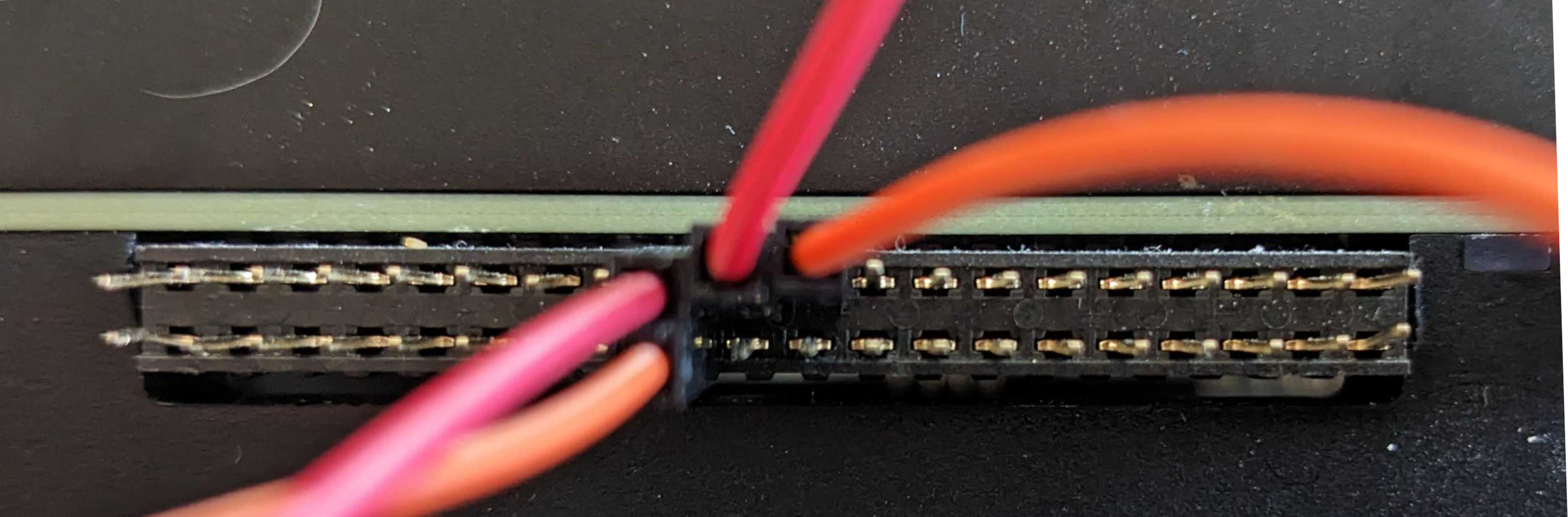
Do the following connections on the pin header:

  • Pin PZ.03 ↔ PZ.04
  • Pin PZ.06 ↔ PZ.05

Software setup

Boot and do the system set-up. Copy gpio-test.ko to the device. Change to root user with sudo -i. The following commands should be run as root. Insert the module with:

insmod gpio-test.ko

Export GPIO pins 495 (Port Z Pin 3) and 498 (Port Z Pin 6) to user space and set them to output low:

echo 495 > /sys/class/gpio/export
echo 498 > /sys/class/gpio/export

echo out > /sys/class/gpio/PZ.03/direction
echo out > /sys/class/gpio/PZ.06/direction

echo 0 > /sys/class/gpio/PZ.03/value
echo 0 > /sys/class/gpio/PZ.06/value

Setup overview

The current setup is now following:

  • PZ.06 is connected to PZ.05. PZ.05 is set to INT0 in tegra194-mb1-bct-gpioint-p2888-0000-p2822-0000.cfg
  • PZ.03 is connected to PZ.04. PZ.04 is set to INT1 in tegra194-mb1-bct-gpioint-p2888-0000-p2822-0000.cfg
  • There is a driver that listens to rising edge interrupts on PZ.04 and PZ.05.

The test

The assumption is following: if we set PZ.06 high, we get an interrupt on PZ.05. If we set PZ.03 high, we get an interrupt on PZ.04. These interrupts should not have anything in common, other than being in the same interrupt controller port Z.

We can check the interrupts seen by the gpio-test driver with:

cat /proc/interrupts | grep gpio-test
287:          0          0          0          0      gpio 161 Edge      gpio-test-isr1
288:          0          0          0          0      gpio 162 Edge      gpio-test-isr2

So far there are no interrupts. Now, let’s set PZ.06 high and check again:

echo 1 > /sys/class/gpio/PZ.06/value
cat /proc/interrupts | grep gpio-test
287:          0          0          0          0      gpio 161 Edge      gpio-test-isr1
288:          1          0          0          0      gpio 162 Edge      gpio-test-isr2

So far so good, now let’s try PZ.03:

echo 1 > /sys/class/gpio/PZ.03/value
cat /proc/interrupts | grep gpio-test
287:          0          0          0          0      gpio 161 Edge      gpio-test-isr1
288:          1          0          0          0      gpio 162 Edge      gpio-test-isr2

We get no interrupt. However, if we now cause an interrupt on PZ.05 by toggling PZ.06, we get both interrupts at the same time:

echo 0 > /sys/class/gpio/PZ.06/value
echo 1 > /sys/class/gpio/PZ.06/value
cat /proc/interrupts | grep gpio-test
287:          1          0          0          0      gpio 161 Edge      gpio-test-isr1
288:          2          0          0          0      gpio 162 Edge      gpio-test-isr2

So the interrupts are now linked in a way that triggering the INT0 interrupt triggers the interrupt in INT1 too, if INT1 was triggered in the meantime. INT1 intterrupt does not trigger without INT0 triggering.

Attachments

Device tree overlay: gpiotest.dtbo (511 Bytes)
GPIO test driver: gpio-test.ko (342.3 KB)

Device tree overlay source: gpiotest.dts (624 Bytes)
GPIO test driver source: gpio-test.c (1.5 KB)

1 Like

@KevinFFF are my steps to reproduce clear? Have you provided them further for testing the issue?

Thanks for your detailed reproduce steps. We are working on reproducing the issue on the devkit and will let you know once there’s any result.

Checking in whether there is any progress. This issue is critical for the product we’re developing.

The Linux driver will check if a controller’s configuration has been locked down, which would imply that something else has already configured the interrupt routing. If so, it won’t touch the configuration. However, if the controller configuration is not locked down yet, it will assume that nothing has configured the interrupt routing yet and will program a default mapping (which will route everything to each controller’s interrupt #0).

Do you lock down the interrupt controller configuration via the BCT?
It would cause the driver to not touch the interrupt routing.

Is there any issue if you are using both INT0 and INT1, and they are both enabled?

I don’t do anything else than what is described in the above steps to reproduce the issue.

Is the default configuration locking down the interrupt controller via the BCT? If not, how do I do that?

There is an issue when using both INT0 and INT1, described in the above steps to reproduce. I don’t know if they are both enabled, how do I check that?

@KevinFFF could you please answer the aforementioned questions?

@KevinFFF could you, or someone else, please answer the aforementioned questions?

@KevinFFF this issue is still not resolved. Poking here again to keep the thread from going stale.

Still waiting for answers.

Sorry for the late reply due to holidays and check with internal.

MB1 configures the interrupt mapping for all GPIO pins. Each GPIO controller has 8 interrupt outputs to send the interrupts to different CPUs/Co-processors. The interrupt routing register configuration determines which pin interrupt is sent to which CPU/Processor. Interrupt 0 is routed to CCPLEX/BPMP and the other interrupts are routed to APE, SPE, SCE and RCE. Also, LIC forwards CCPLEX bound interrupts to timestamping engines. If the interrupts are not bound to CCPLEX, then the timestamping engines will not be detecting the interrupts.

If you wish to rely on procfs for interrupts count, then all interrupts should be mapped to CCPLEX only. Mapping them to other processors would mean CCPLEX cannot detect those interrupts.

Hi. Thanks for the reply.
Does this mean that using LIC interrupts there isn’t a way to determine which GPIO pin caused the interrupt? Mapping them to CCPLEX will cause all interrupts to have the same interrupt number, am I right?

Yes, the interrupts from different GPIO pins under the same GPIO controller are aggregated. Based on the HW architecture, if all the pins interrupts are routed to single GPIO controller interrupt, then there would be a single interrupt routed to LIC. The status registers would indicate if there are interrupts on multiple GPIO pins

This topic was automatically closed 14 days after the last reply. New replies are no longer allowed.

Please just keep using INT0 for both PZ.05 and PZ.04.
In this way, you would not hit this issue and the interrupt counts should be expected.