USB 3.0 Device port

Hi,
We have our custom carrier board for Jetson Nano.
On that we have given USB3.0 type A connector.
By default can connector is Host port (sourcing supply).
That works fine.
Now we had new requirement that the same port we want to operate in Device mode.
According to that we made hardware changes related to VBUS sensing.
Also we made the changes in dtsi files. (please find the attachments.)
After doing all this if we connect that port to host it gets detected as device.
But only issue that it detect as USB2 device not as USB3 device. We have not change the specification of USB 2-1 port but it work only in USB2.0 mode.
Please guide us on that.

With regards,
Rahul.
DTSI_CHANGE.txt (3.3 KB)

Hi,
Since type-A port is a host-only port, it may not work properly if you run it in device mode. We suggest have a correct hardware design such as micro-B port. And use the type-A port in host mode.

Hello DaneLLL,
Thank you so much for reply.
As on dev kit for device port micro -B connector has been given but if you check its connection
ID pin is not used.
In our case also we dont want to achieve OTG operation we want our port suppose to be act as only device port just like USB 2- 0 in dev kit.
And as such its working ,I can able to connect my carrier board to host (USB 3.0 port of laptop) and through headless mode I can able to login in.
Only thing its in USB 2.0 mode , ideally it suppose to be USB 3.0 device mode.

Hi,
On Jetson Nano developer kit, VBUS pin in the micro B port is used to decide if it goes to device mode. This may not work in type A port.

I know a lot more about USB 2 than 3, but the PHY is actually different in USB 3. What you’re describing sounds like you want a dedicated USB 3 device mode, which in turn implies you want a type-B connector. It would be possible to miswire a USB 2 type-A connector and treat it as a type-B if you don’t mind violating standards, but there is more to the story when transitioning from USB 2 to USB 3 beyond just a speed increase. There are other wires involved which don’t exist in USB 3.

In a normal (properly operating) USB 3 connector, at the host side, it still operates in USB 2 mode unless it has detected a USB 3 device. You say the host is a laptop, and so it is the laptop which determines if this is USB 2 or USB 3. The way it does this is in part by wiring. What kind of socket does the laptop have? Did you provide all of the wires to the laptop such that it is actually capable of USB 3 mode?

Here is a Wikipedia USB 3 type-A socket, one of which might be on the laptop (the laptop will have either type-A or type-C):

Here is a Wikipedia USB 2 type-A socket:

Notice that for a USB 2 connection that the host always needs a ground, and a data+/data- pair. To achieve USB 3 you’d need another 5 wires (label is USB 2 pins wires #1-4, and USB 3 pins wires #5-9). Did you somehow wire the extra 5 pins into the cable? I know the USB 2 connector at the Jetson end (unless you made it a USB 3 connector) won’t have this.

Also keep in mind that in the days of USB 2 a single controller handled USB 1.0, 1.1., and 2.0 (and switches between modes). For the case of USB 3 any USB 2 devices are routed to a USB 2 controller, and a USB 3 device is routed to the dedicated USB 3 controller. Unless the controller thinks the device is USB 3 the host will never allow it to operate in USB 3 mode, and it is the host which makes that decision. Even if the wiring is present, if the signal quality is not sufficient, then it will revert back to USB 2 mode if the device allows it (and if the device does not allow it, then it will disconnect from the bus).

I wish I knew enough about USB 3 to help more, but unless you’ve wired this as USB 3, then even if the device is capable of operating in USB 3 mode there will be only USB 2 mode. Even if the wiring is present, if the device uses the wrong controller, then it will also be only USB 2.

Hello All,
Thanks a lot for comment.
Sorry for my previous comments.
Actually there was discontinuety issue with my old USB 3.0 type A to type A cable.
I checked with new USB 3.0 type A to type A cable. It shows following connections.


But after using this cable I faced another issue.
When I use USB 2.0 type A to type A cable to connect carrier board to host (laptop USB 3.0 port) its been get detected and it shows following details on terminal

But when I am using USB 3.0 type A to type A cable to connect carrier board to host (laptop USB 3.0 port) its not been detected.

I checked from SOM to host USB 3.0 connection RX and TX lines are crossed in cable only.
I think connection is ok.
Please guide me on this.

With regards,
Rahul.

Keep in mind that the above is a violation of standards. You won’t find documentation on this. I don’t know enough to validate USB 3 wiring, but documents on either USB 3.0 or USB 3.1 gen. 1 type-A to type-B wiring are what you’ll need. One end of the type-A will need to pretend it is talking to a type-B socket. Somewhere in that would be the key to what must be done at the Jetson side (in combination with a cable modification) to make it possible for the Jetson to be seen as USB 3 if it is running as a USB 3 device (and probably a combination of wiring and device tree would be used to actually cause the Jetson to run as both device mode and USB 3 speed, but I’ve never attempted this).

FYI, the “lsusb -t” does not show any errors. It just says all devices detected are only capable of USB 2 or slower (which could include a USB 3 device with insufficient signal quality; the trick is to look at the “dmesg --follow” as you plug in the Jetson in device mode to see what the host is doing, and to also include the “dmesg --follow” from the Jetson end at the same moment of plugin…this might offer clues to mode switching, but “lsusb -t” will never tell you this information).

If a “normal” situation is used, not modified like in this case, then a USB 2 device talking to a USB 3 type-A port will use only the original 4 wires of USB 2 (GND, D+, D-, and +5V). A USB 3 device on a USB 3 type-A port will use 5 more wires. I don’t know how the logic works with those extra wires to tell you what must be done to trick it into always being USB 3 mode. Consider though that a “standard” USB 3 device (the device end connector) will also use those extra wires, and that if a purely USB 2 cable is used without those extra wires, then the device will revert to USB 2 mode despite being perfectly capable of USB 3 and despite a perfect signal quality.

If you really want to go this route you probably will need a USB 3 logic analyzer. Especially, if like myself, you have detailed knowledge of how USB 3 modifies USB 2.

Incidentally, if you look at a type-A USB 3 connector and socket with numbering:

In those diagrams there is no crossover of D+ to D-, it is direct D+ to D+ and D- to D-. D- is always pin 2. D+ is always pin 3. If we were talking about a full duplex wiring, then you would have crossover (e.g., like ethernet). However, USB is not 2-way, and the signal is a balanced pair. I suppose there might at some place in USB 3 be a specification to allow D+ to D-, but I am unaware of it. Definitely though a D+ to D+ and D- to D- is shown in the actual type-A to type-B (which is what the standard uses).

I don’t know if it is possible, but if you are working with a custom carrier board, then why not put an actual type-B connector in (USB 3, not a micro-OTG, although there is a USB 3 micro-B)? Unless you are just experimenting, any consideration of shipping something which uses type-A to type-A (a standards violation) is asking for trouble when someone uses a standard cable or does not understand the device mode on a type-A socket (this is the violation of standards).

Hello ,
Sorry about delayed response.
Normally if you check few PTZ camera where they had given USB 3.0 port as type A only so to connect them we need USB 3.0 Type A to Type A cables.
As we developed our carrier board for multipurpose things so in some of application we require USB 3.0 host port because of that we put Type A connector only on carrier board.
Here I try to study the dmesg data related to USB after connecting our carrier board.
But nothing is appeared for USB 3 everything is for USB 2 and USB 1.1 only.(please check attachment)
As we only concentrate on changing DTS to make USB 3.0 device port .
Is there any role of drivers to change Nvidia SOMs USB functionalily?
Means Nvidia USB device port drivers are only support USB 2.0 specification and not USB 3.0 specification.
Shall we need to modify USB drivers also?
Please guide me on this.
USB_DEBUG.txt (7.9 KB)

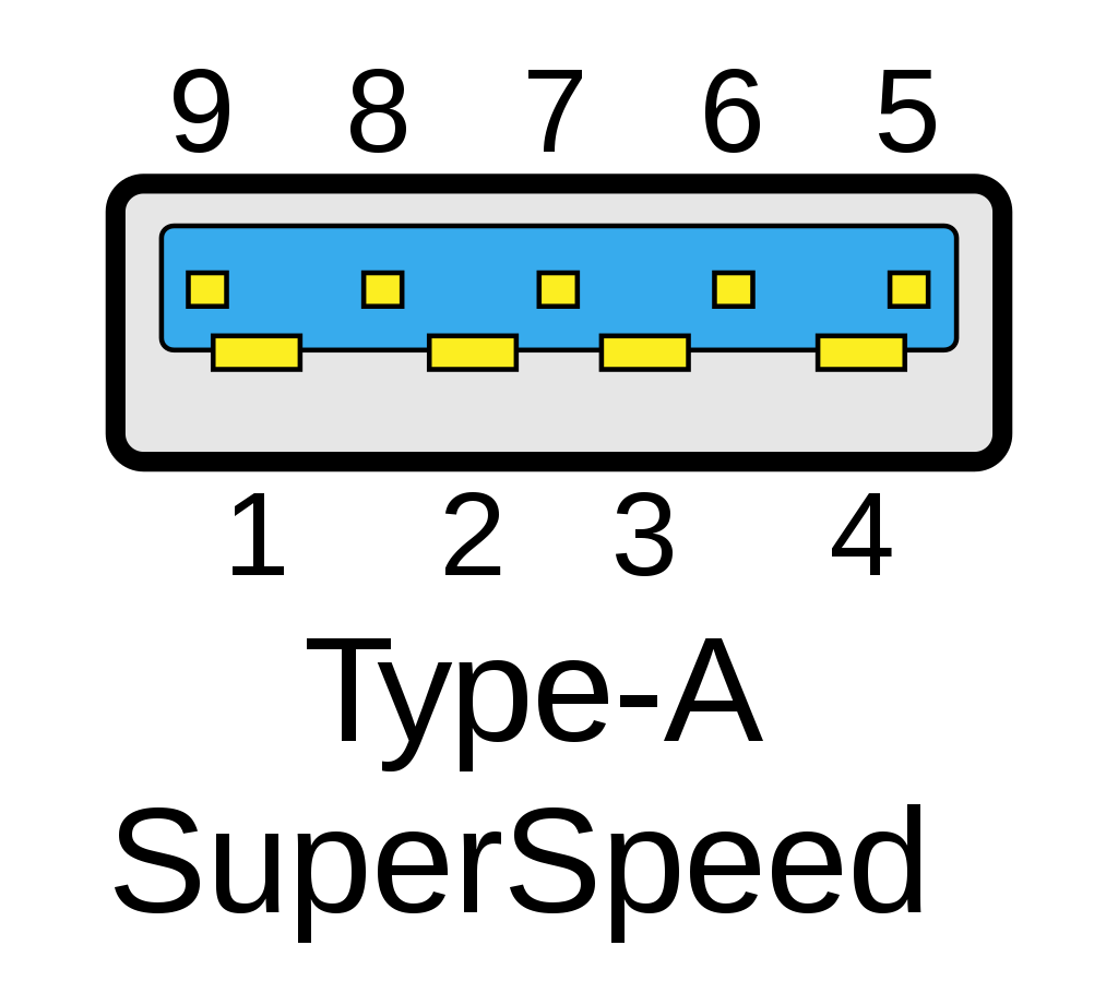
If a camera is a USB device (and not a host), then it is a violation of standards to use a type-A connector. It really needs a type-B. Looking closer at your wiring diagram it shows pin #2 for both D+ and D- of plug #2, and I assume that is a typographic error (it says D+ and D- are shorted). Can you verify though if it is D+ of the left connector to D+ of the right connector? If it is D+ to D- I suspect it won’t work.

In the case of the USB 3 wires I don’t know if that would work or not, although likely it would work. What does your USB 3 logic analyzer say (do you have an analyzer, it would be quite helpful)? Is there activity on the USB 3 wiring, or is the activity all on the USB 2 wiring? If the former, then the controller is probably configured correctly, and something else is telling it to fall back; however, if it is the latter, then perhaps either wiring or controller is in the wrong configuration.

As a test, assuming the Jetson has a standard USB 3 type-A host port, why not try plugging in other USB 3 devices to see if they work at USB 3 speed? Is it just one device failing, or is it all USB 3 devices?

Incidentally, you should never connect a type-A host port to another type-A host port (in theory you are connecting a type-A host to a type-A device, but Jetson to laptop type-A to type-A is a bad idea). This is not full duplex hardware. One end must be a master. In the case of USB 3 type-C it is a bit of an illusion that the cable is full duplex. When USB 3.1 gen. 2+ is used there are extra data wires, and each half is one-way (with a host/master and device/slave) despite being able to configure each half to become host or device (sorry, my USB 3 is not so great, “I’m a USB 2 guy”). It isn’t full duplex despite having two USB lines if that makes sense (not sure I’m describing it correctly, but two independent USB data paths are still independent balanced pairs and not full duplex with TX/RX just because they are in the same cable).

The device tree does change what controller is available. One controller handles legacy (USB2 or older), while another controller handles USB3+. If USB3 is enabled, it implies certain conditions of the connected device will cause routing to the USB3 controller when it is enabled, but failure of those conditions will route instead to the USB2 controller. Failing either the device tree configuration or failing the other wiring states will cause routing to a USB2 controller. Thus I asked if any of the USB3 devices work as USB3.

You might also extract your device tree and post that:
dtc -I fs -O dts -o extracted_tree.dts /proc/device-tree
(then attach extracted_tree.dts; you could bzip/gzip it if you want)

I won’t be able to answer what device tree changes are needed, but I can guarantee that if the wiring is wrong, then it won’t allow it even if the device tree is correct. I strongly suggest checking with a logic analyzer and also never using a type-A to type-A cable between two hosts.

Hello,
Actually in our case though its Type A connector but when I use it for device port mode I remove +5V supply from VBUS pin and connect device detection circuit for sensing external device.
As per your suggestion I try to carefully observe the dmesg while connecting the USB cable from our custom carrier board to host.
Please check the attached dmesg data log where I separate out the messages when I use USB 3.0 cable and USB 2.0 cable to connect the host.
When I try to connect through USB 3.0 cable device wont get detected but when I connect through USB2.0 cable its been detected.
I checked my Laptops device USB 3.0 port its working with all the other USB 3.0 devices like portable harddisk and cameras.
Here I have attached device tree also.
It reflect all the dtsi changes related to USB but its we can able to detect device in USB 2.0 mode only.
Using DSO I try to check the signals in USB 3.0 device connections.
On D+ and D- I saw regular data pulses but RX and TX signals I am not getting anything.
nano_usb_device.txt (8.4 KB)
extracted_tree.dts (321.4 KB)
Please guide me on this.

Although I can’t answer this, I have seen similar errors from “normally wired” ports (presumably when signal quality was not sufficient). However, I do not know what the specific “-71” error is (perhaps NVIDIA has access to the meaning of that specific error). Even if your wiring is correct it might not have tight enough tolerances. I really suggest a logic analyzer on this.

The USB 2 device has no such issue, but also a USB 2 device has no need of some of the wires (the D+/D- is apparently wired correctly and within tolerance).

This topic was automatically closed 14 days after the last reply. New replies are no longer allowed.