I have a commercial carrier board for AGX orin with 1 sensor camera port,sensor is imx219. I’m using Jetpack 36.3
V4L2 works well,but Argus does not detect sensors。


sudo dtc -I fs -O dts -o extracted_proc.dts /proc/device-tree
extracted_proc.zip (48.9 KB)

argus-output.log (2.1 KB)
Looks like your device tree still keep like JP5.
hi,
I confirm that my version is JP36.3, and the configuration in the pulled down project code is as follows:
tegra234-p3767-camera-p3768-imx219-A.dts:
tegra-camera-platform {
compatible = “nvidia, tegra-camera-platform”;
/**
* Physical settings to calculate max ISO BW
*
* num_csi_lanes = <>;
* Total number of CSI lanes when all cameras are active
*
* max_lane_speed = <>;
* Max lane speed in Kbit/s
*
* min_bits_per_pixel = <>;
* Min bits per pixel
*
* vi_peak_byte_per_pixel = <>;
* Max byte per pixel for the VI ISO case
*
* vi_bw_margin_pct = <>;
* Vi bandwidth margin in percentage
*
* max_pixel_rate = <>;
* Max pixel rate in Kpixel/s for the ISP ISO case
*
* isp_peak_byte_per_pixel = <>;
* Max byte per pixel for the ISP ISO case
*
* isp_bw_margin_pct = <>;
* Isp bandwidth margin in percentage
/
num_csi_lanes = <4>;
max_lane_speed = <1500000>;
min_bits_per_pixel = <10>;
vi_peak_byte_per_pixel = <2>;
vi_bw_margin_pct = <25>;
max_pixel_rate = <7500000>;
isp_peak_byte_per_pixel = <5>;
isp_bw_margin_pct = <25>;
/*
* The general guideline for naming badge_info contains 3 parts, and is as follows,
* The first part is the camera_board_id for the module; if the module is in a FFD
* platform, then use the platform name for this part.
* The second part contains the position of the module, ex. “rear” or “front”.
* The third part contains the last 6 characters of a part number which is found
* in the module’s specsheet from the vendor.
*/
modules {
cam_module0: module0 {
badge = “jakku_front_RBP194”;
position = “front”;
orientation = “1”;
cam_module0_drivernode0: drivernode0 {
pcl_id = “v4l2_sensor”;
sysfs-device-tree = “/sys/firmware/devicetree/base/bus@0/cam_i2cmux/i2c@0/rbpcv2_imx219_a@10”;
};
cam_module0_drivernode1: drivernode1 {
pcl_id = “v4l2_lens”;
sysfs-device-tree = “/sys/firmware/devicetree/base/bus@0/lens_imx219@RBPCV2”;
};
};
};
};
the solution in this blow case
R36.3: “No cameras available” when using GStreamer with nvarguscamerasrc is:

and my dts configuration is:
tegra-camera-platform {
compatible = “nvidia, tegra-camera-platform”;
status = “okay”;
/**
* Physical settings to calculate max ISO BW
*
* num_csi_lanes = <>;
* Total number of CSI lanes when all cameras are active
*
* max_lane_speed = <>;
* Max lane speed in Kbit/s
*
* min_bits_per_pixel = <>;
* Min bits per pixel
*
* vi_peak_byte_per_pixel = <>;
* Max byte per pixel for the VI ISO case
*
* vi_bw_margin_pct = <>;
* Vi bandwidth margin in percentage
*
* max_pixel_rate = <>;
* Max pixel rate in Kpixel/s for the ISP ISO case
*
* isp_peak_byte_per_pixel = <>;
* Max byte per pixel for the ISP ISO case
*
* isp_bw_margin_pct = <>;
* Isp bandwidth margin in percentage
/
num_csi_lanes = <4>;
max_lane_speed = <25000000>;
min_bits_per_pixel = <10>;
vi_peak_byte_per_pixel = <2>;
vi_bw_margin_pct = <25>;
max_pixel_rate = <240000>;
isp_peak_byte_per_pixel = <5>;
isp_bw_margin_pct = <25>;
/*
* The general guideline for naming badge_info contains 3 parts, and is as follows,
* The first part is the camera_board_id for the module; if the module is in a FFD
* platform, then use the platform name for this part.
* The second part contains the position of the module, ex. “rear” or “front”.
* The third part contains the last 6 characters of a part number which is found
* in the module’s specsheet from the vendor.
*/
modules {
cam_module0: module0 {
status = “okay”;
badge = “jakku_front_RBP194”;
position = “front”;
orientation = “1”;
drivernode0 {
status = “okay”;
pcl_id = “v4l2_sensor”;
sysfs-device-tree = “/sys/firmware/devicetree/base/bus@0/i2c@3180000/tca9546@70/i2c@0/z_imx219_96717_a”;
};
					drivernode1 {
					        status = "okay";
						pcl_id = "v4l2_lens";
						sysfs-device-tree = "/sys/firmware/devicetree/base/bus@0/lens_imx219@RBPCV2";
					};

				};
			};
		};
Doesn’t see your camera from your device tree dump.
Below is from your attached file in your previous comment
                        module0 {
                                badge = "custom_front_ar0234";
                                position = "front";
                                orientation = "0";
                                phandle = <0x2aa>;

                                drivernode0 {
                                        devname = "sh_ar0234 30-0021";
                                        proc-device-tree = "/proc/device-tree/i2c@3180000/tca9548@77/i2c@0/custom_ar0234_a@21";
                                        pcl_id = "v4l2_sensor";
                                        phandle = <0x2ab>;
                                };
                        };
hi,
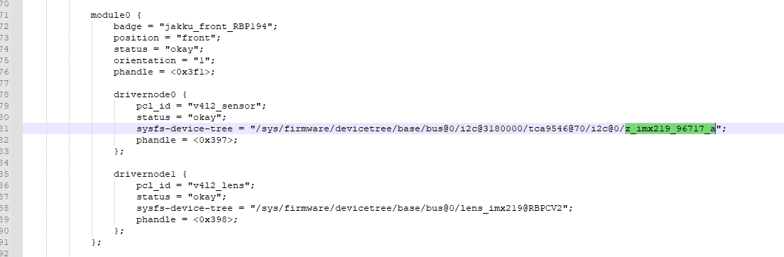
I double confirm, module 0 is:
         module0 {
			badge = "jakku_front_RBP194";
			position = "front";
			status = "okay";
			orientation = "1";
			phandle = <0x3f1>;

			drivernode0 {
				pcl_id = "v4l2_sensor";
				status = "okay";
				sysfs-device-tree = "/sys/firmware/devicetree/base/bus@0/i2c@3180000/tca9546@70/i2c@0/z_imx219_96717_a";
				phandle = <0x397>;
			};

			drivernode1 {
				pcl_id = "v4l2_lens";
				status = "okay";
				sysfs-device-tree = "/sys/firmware/devicetree/base/bus@0/lens_imx219@RBPCV2";
				phandle = <0x398>;
			};
		};
in my device tree dump
extracted_proc.zip (48.9 KB)
What’s the v4l2-ctl --all shows?
v4l2-ctl --all
Driver Info:
Driver name : tegra-video
Card type : vi-output, z_imx219_96717 9-001
Bus info : platform:tegra-capture-vi:0
Driver version : 5.15.136
Capabilities : 0x84200001
Video Capture
Streaming
Extended Pix Format
Device Capabilities
Device Caps : 0x04200001
Video Capture
Streaming
Extended Pix Format
Media Driver Info:
Driver name : tegra-camrtc-ca
Model : NVIDIA Tegra Video Input Device
Serial :
Bus info :
Media version : 5.15.136
Hardware revision: 0x00000003 (3)
Driver version : 5.15.136
Interface Info:
ID : 0x03000008
Type : V4L Video
Entity Info:
ID : 0x00000006 (6)
Name : vi-output, z_imx219_96717 9-001
Function : V4L2 I/O
Pad 0x01000007 : 0: Sink
Link 0x0200000c: from remote pad 0x1000003 of entity ‘13e00000.host1x:nvcsi@15a00000-’ (Unknown sub-device (0002000a)): Data, Enabled
Priority: 2
Video input : 0 (Camera 0: ok)
Format Video Capture:
Width/Height : 1920/1080
Pixel Format : ‘RG10’ (10-bit Bayer RGRG/GBGB)
Field : None
Bytes per Line : 3840
Size Image : 4147200
Colorspace : sRGB
Transfer Function : Default (maps to sRGB)
YCbCr/HSV Encoding: Default (maps to ITU-R 601)
Quantization : Default (maps to Full Range)
Flags :
Camera Controls
                sensor_mode 0x009a2008 (int64)  : min=0 max=1 step=1 default=0 value=0 flags=slider
       sensor_configuration 0x009a2032 (u32)    : min=0 max=4294967295 step=1 default=0 dims=[22] flags=read-only, volatile, has-payload
     sensor_mode_i2c_packet 0x009a2033 (u32)    : min=0 max=4294967295 step=1 default=0 dims=[1026] flags=read-only, volatile, has-payload
  sensor_control_i2c_packet 0x009a2034 (u32)    : min=0 max=4294967295 step=1 default=0 dims=[1026] flags=read-only, volatile, has-payload
                bypass_mode 0x009a2064 (intmenu): min=0 max=1 default=0 value=0 (0 0x0)
                            0: 0 (0x0)
                            1: 1 (0x1)
            override_enable 0x009a2065 (intmenu): min=0 max=1 default=0 value=0 (0 0x0)
                            0: 0 (0x0)
                            1: 1 (0x1)
               height_align 0x009a2066 (int)    : min=1 max=16 step=1 default=1 value=1
                 size_align 0x009a2067 (intmenu): min=0 max=2 default=0 value=0 (1 0x1)
                            0: 1 (0x1)
                            1: 65536 (0x10000)
                            2: 131072 (0x20000)
           write_isp_format 0x009a2068 (int)    : min=1 max=1 step=1 default=1 value=1
   sensor_signal_properties 0x009a2069 (u32)    : min=0 max=4294967295 step=1 default=0 dims=[30][18] flags=read-only, has-payload
    sensor_image_properties 0x009a206a (u32)    : min=0 max=4294967295 step=1 default=0 dims=[30][16] flags=read-only, has-payload
  sensor_control_properties 0x009a206b (u32)    : min=0 max=4294967295 step=1 default=0 dims=[30][36] flags=read-only, has-payload
          sensor_dv_timings 0x009a206c (u32)    : min=0 max=4294967295 step=1 default=0 dims=[30][16] flags=read-only, has-payload
           low_latency_mode 0x009a206d (bool)   : default=0 value=0
           preferred_stride 0x009a206e (int)    : min=0 max=65535 step=1 default=0 value=0
               sensor_modes 0x009a2082 (int)    : min=0 max=30 step=1 default=30 value=1 flags=read-only
The address looks like incorrect. The slave address should be 9-0010 instead of 9-001.
Maybe modify the z_imx219_96717_a{} to z_imx219_96717_a@10 {}
Name : vi-output, z_imx219_96717 9-001
hi,
I have modify the z_imx219_96717_a{} to z_imx219_96717_a@10 {}, and dump dtsi confirm it has take effect,but v4l2-ctl --all:
~/l00013293$ v4l2-ctl --all
Driver Info:
Driver name : tegra-video
Card type : vi-output, z_imx219_96717 9-001
Bus info : platform:tegra-capture-vi:0
Driver version : 5.15.136
Capabilities : 0x84200001
Video Capture
Streaming
Extended Pix Format
Device Capabilities
Device Caps : 0x04200001
Video Capture
Streaming
Extended Pix Format
Media Driver Info:
Driver name : tegra-camrtc-ca
Model : NVIDIA Tegra Video Input Device
Serial :
Bus info :
Media version : 5.15.136
Hardware revision: 0x00000003 (3)
Driver version : 5.15.136
Interface Info:
ID : 0x03000008
Type : V4L Video
Entity Info:
ID : 0x00000006 (6)
Name : vi-output, z_imx219_96717 9-001
Function : V4L2 I/O
Pad 0x01000007 : 0: Sink
Link 0x0200000c: from remote pad 0x1000003 of entity ‘13e00000.host1x:nvcsi@15a00000-’ (Unknown sub-device (0002000a)): Data, Enabled
Priority: 2
Video input : 0 (Camera 0: ok)
Format Video Capture:
Width/Height : 1920/1080
Pixel Format : ‘RG10’ (10-bit Bayer RGRG/GBGB)
Field : None
Bytes per Line : 3840
Size Image : 4147200
Colorspace : sRGB
Transfer Function : Default (maps to sRGB)
YCbCr/HSV Encoding: Default (maps to ITU-R 601)
Quantization : Default (maps to Full Range)
Flags :
Camera Controls
                sensor_mode 0x009a2008 (int64)  : min=0 max=1 step=1 default=0 value=0 flags=slider
       sensor_configuration 0x009a2032 (u32)    : min=0 max=4294967295 step=1 default=0 dims=[22] flags=read-only, volatile, has-payload
     sensor_mode_i2c_packet 0x009a2033 (u32)    : min=0 max=4294967295 step=1 default=0 dims=[1026] flags=read-only, volatile, has-payload
  sensor_control_i2c_packet 0x009a2034 (u32)    : min=0 max=4294967295 step=1 default=0 dims=[1026] flags=read-only, volatile, has-payload
                bypass_mode 0x009a2064 (intmenu): min=0 max=1 default=0 value=0 (0 0x0)
                            0: 0 (0x0)
                            1: 1 (0x1)
            override_enable 0x009a2065 (intmenu): min=0 max=1 default=0 value=0 (0 0x0)
                            0: 0 (0x0)
                            1: 1 (0x1)
               height_align 0x009a2066 (int)    : min=1 max=16 step=1 default=1 value=1
                 size_align 0x009a2067 (intmenu): min=0 max=2 default=0 value=0 (1 0x1)
                            0: 1 (0x1)
                            1: 65536 (0x10000)
                            2: 131072 (0x20000)
           write_isp_format 0x009a2068 (int)    : min=1 max=1 step=1 default=1 value=1
   sensor_signal_properties 0x009a2069 (u32)    : min=0 max=4294967295 step=1 default=0 dims=[30][18] flags=read-only, has-payload
    sensor_image_properties 0x009a206a (u32)    : min=0 max=4294967295 step=1 default=0 dims=[30][16] flags=read-only, has-payload
  sensor_control_properties 0x009a206b (u32)    : min=0 max=4294967295 step=1 default=0 dims=[30][36] flags=read-only, has-payload
          sensor_dv_timings 0x009a206c (u32)    : min=0 max=4294967295 step=1 default=0 dims=[30][16] flags=read-only, has-payload
           low_latency_mode 0x009a206d (bool)   : default=0 value=0
           preferred_stride 0x009a206e (int)    : min=0 max=65535 step=1 default=0 value=0
               sensor_modes 0x009a2082 (int)    : min=0 max=30 step=1 default=30 value=1 flags=read-only
extracted_proc_0805.zip (48.9 KB)
hi,
this is GMSL camera,sensor:imx219,serializer:MAX96717,Deserializer:MAX96712
Suppose the slave address should be 0x10 but it shows 0x01 in the Name item.
What’s the dmesg show the slave address?
sudo dmesg | grep -i imx219

This message shows the device slave address is 0018 on bus 9.
How should I modify the dtsi?
Confirm the slave address then make sure modify all of the z_imx219_96717_a modify to z_imx219_96717_a@18