Hi there, thank you for the attention.
I’m currently working on a physics based approach very similar to the cylinder_2d.py example.
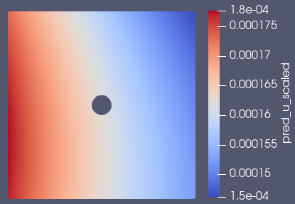
The key difference is that my domain is in the microscale (only 60x60 µm, Cylinder 7 µm) and my fluid has a density of about 1000 kg/m³ and is highly viscous at about 0.05 kg/(m*s).
The problem is that the trained model does not even show flow around a cylinder (as can be seen in the image below). In some cases it even seems that the cylinder is not taken into account when using a microscale domain.
My idea was using the nonDimensionalizer to scale the values, but I couldn’t find any solution for this either. From my point of view, the reason for this seems to be the microscale.
Any idea how to solve this problem? Can Modulus produce good results at the microscale?
Many thanks in advance!
Hi @jflatter
Yes, the scaling of the problem can be very important. You should non-dimensionalize or scale your system which may require some experimenting.
However another option to try is integral planes which are used in a number of out flow problems. The idea is to create an integral constraint that will force mass flow rate to be correct across different cross sections of the flow domain. We find these can help with flow related problems.
A simple example this is in the annular ring problem and there’s information on these in our user-guide.
1 Like
Hi @ngeneva
Thank you for your answer.
I have already tried to use the nonDimensionalizer, but I often get the error message that the geometry has no surface. I looked at the source code, but I couldn’t figure out how the non-dimensional values are calculated in detail.
For example, I have defined a value of 0.00003 m and a lenght-scale of 10 m: How does the nonDimensionalizer calculate the non-dimensionalized value in this example?
Many thanks in advance!
Hi @jflatter
I am not sure what would cause that error message. The cylinder example provides an example of this utility. Also the non-dimensionalizer code uses Pint under the hood. So perhaps those docs can also help guide you.
Hi @ngeneva
Thank you for your answer, I’ve figured it out now. The values you set are devided with the scaling parameters.
But I have another question regarding the continuity planes. How can I set planes on different cross sections in the channel? I tried to use following code, but all planes were generated at the outlet:
criteria=Eq(x, channel_length[1]),
And is there a list of possible outvar criterias? I have only seen the pressure, velocities and the NormalDotVec as criterias.
Thanks in advance!
1 Like
HI @jflatter
The criteria is a geometric criteria that is a sympy expression. This defines how to sub-sample the geometry, thus isn’t related to the flow variables. The flow variables (in/outlet boundary condition) are defined via the outvar (target) variables which can be a variety of boundary conditions.
So the example you provided constrains the geometry to just the outlet where x == channel_lenght[1]. This is on the boundary of the domain (assuming boundary constraint) so it will not be able to sample the interior at certain cross sections.
If you have a interior domain where you want to train on some specific cross sections. I would suggest you define a seperate geometry with just these cross-sections then use a PointwiseInteriorConstraint to impose any conditions you have. (There are also examples that have integral planes that use cross section)
E.g. If my domain is a rectangle, this cross-section geometry may be a union of 2D lines at specific locations. I would then use the new geometry in a interior constraint to impose conditions needed.
1 Like
Hi @ngeneva
Thank you again. This makes perfect sense to me.
I will give it a try.