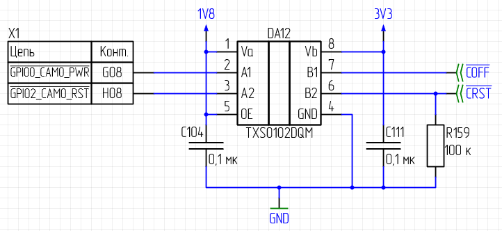
We developed our custom carrier board. We need to control powerdown and reset functions of some ICs with 3v3 io levels. So we placed a level-shifter, TI TXS0102, and used two of Jetsons GPIOs: G8 for powerdown, and H8 for reset, as shown on scheme below.
Inside the level shifter there are embedded 10k pull-ups on each line, to 1v8 on jetson side and to 3v3 on ICs side.
So we need to pull the lines down to GND by Jetson’s G8 and H8. And we managed to do it just fine, but only with G8-pwrdn. And no mater what we do, it is always 1v8 on H8, even if the system shows the pin state as low.
We think it is because G8 has pull-down on-module, while H8 has pull-up in standard configuration. So we tried re-configure that with pinmux scripts and re-bulding the core, but with no effect.
Can you please suggest optimal pin configuration of GPIO that need to actively pull down its line? And how to correctly implement that configuration?
after you configure the pinmux spreadsheets, you should copy the generated *.dtsi files for conversion.
please execute dts2cfg tool, it converts pinmux, gpio and pad dts file into cfg format.
check the documentation for details, i.e. $OUT/Linux_for_Tegra/kernel/pinmux/t186/README.txt
please use the new cfg file, and perform a complete flashing process to update the board configuration.
thanks
We configured H8 as pull-down output in pinmux sheet, generated the dtsi-files, converted them to cfg, build new core and flashed it to jetson. Flashing was complete.
And then, after the flashing, H8 pin is still unable to pull the line down.
We also tried pull-none drive-0 combination in pinmux, and checked another, out-of-box new jetson. The issue remains.
could you please share the board configuration file of these two pins,
for example, $OUT/Linux_for_Tegra/bootloader/t186ref/BCT/tegra186-mb1-bct-pinmux-quill-p3310-1000-c03.cfg
We also tried pin configurations of open-drain and bidirectional.
If pin is configured as open-drain, the jetson does not boot after flashing.
When we configured H8 as bidirectional, with pin state as n/a, it was able to pull the line down to 0v4. BUT-the G8 stopped working properly, even though we did not touched its configuration. Also after rebooting H8 was able to pull the line down only to 1v4 from 1v8. So results are still inconclusive. Even more so.
Hi lipado,
May I know what all changes have you made in kernel device tree to disable these pins to be used by camera?
Also, if you have correctly disabled then you will not see it in /sys/kernel/debug/gpio. Can you confirm?