Jetson Xavier CAM0 reset(GPIO3_PH.03) can not pull HIGH in my lt6911uxc driver probe?

I add the lt6911uxc driver to I2C-8 in device tree.GPIO

[ \hardware\nvidia\platform\t19x\galen\kernel-dts\tegra194-p2888-0001-p2822-0000.dts ]
#include "common/tegra194-p2888-0001-p2822-0000-common.dtsi" 
#include "common/tegra194-p2822-camera-modules.dtsi" 
#include "t19x-common-modules/tegra194-camera-plugin-manager.dtsi" 
#include "common/tegra194-p2822-0000-hdmi2mipi-lt6911uxc-a00.dtsi" // add FPGA driver

[ common/tegra194-p2822-0000-hdmi2mipi-lt6911uxc-a00.dtsi ]
#define LT6911_EN "okay"
/ { 
	/* set lt6911uxc reset and interrupt gpio direction */
	gpio@2200000 { 
	    camera-control-output-low { 
	        status = LT6911_EN;
		gpio-hog;
		output-low;
		gpios = <TEGRA194_MAIN_GPIO(H, 3) 0>;
		label = "cam0-rst"; 
	    };
	     
	    camera-control-input { 
	        status = LT6911_EN;
		gpio-hog;
		input;
		gpios = <TEGRA194_MAIN_GPIO(P, 0) 0>;
		label = "cam0-int"; 
	    }; 
	};
			
	/* i2c-8 */ 		
	i2c@31e0000 { 
	    clock-frequency = <100000>;
	    lt6911uxc_a@2b { 
	        compatible = "lontium,lt6911uxc";
		reg = <0x2b>;
		status = LT6911_EN;
		devnode = "video0";
		/* Reset */
		reset-gpio = <&tegra_main_gpio TEGRA194_MAIN_GPIO(H, 3) GPIO_ACTIVE_HIGH>; 
		
		/* Interrupt */
		interrupt-parent = <&tegra_main_gpio>;
		interrupts = <TEGRA194_MAIN_GPIO(P, 0) IRQ_TYPE_LEVEL_HIGH>;
		port@0 { 
		    ret = <0>;
		    status = LT6911_EN;
		    hdmi2csi_lt6911_out0: 
		        endpoint { 
		            status = LT6911_EN;
			    port-index = <0>;
			    bus-width = <4>;
			    remote-endpoint = <&hdmi2csi_csi_in0>; 
			}; 
		    }; 
		}; 
        };
}

I pull cam0-rst(pin L5, GPIO3_PH.03) to HIGH in lt6911uxc_probe, and read lt6911uxc chip id by I2C-8.

[ \kernel\nvidia\drivers\media\i2c\lt6911uxc.c ]
static int lt6911uxc_probe(struct i2c_client *client, const struct i2c_device_id *id)
{
	struct lt6911uxc_state *state;
	struct v4l2_subdev *sd;
	int err = 0;

	dev_info(&client->dev, "Probing lt6911uxc\n");
	state = devm_kzalloc(&client->dev, sizeof(struct lt6911uxc_state), GFP_KERNEL);
	if (!state)
		return -ENOMEM;

	state->pdata = lt6911uxc_parse_dt(client);
	if (!state->pdata)
		return -ENODEV;

	state->i2c_client = client;
	sd = &state->sd;
	v4l2_i2c_subdev_init(sd, client, &lt6911uxc_ops);

	dev_info(&client->dev, "Chip found @ 7h%02X (%s)\n", client->addr, client->adapter->name);

	// Release CAM_RST Reset (pin L5, GPIO3_PH.03) 
	dev_info(&client->dev, "Releasing CAM_RST Reset (gpio 0x%04X)\n", state->pdata->reset_gpio);
	if (!gpio_is_valid(state->pdata->reset_gpio)) 
	{
		dev_err(&client->dev, "Reset CAM_RST GPIO is invalid!\n");
		return state->pdata->reset_gpio;
	}
	
	err = devm_gpio_request_one(&client->dev, state->pdata->reset_gpio, GPIOF_OUT_INIT_HIGH, "lt6911uxc-reset");
	if (err) 
	{
		dev_err(&client->dev, "Failed to request Reset CAM_RST GPIO 0x%04X: %d\n",
			state->pdata->reset_gpio, err);
		return err;
	}

	// CAM0_RST Reset (pin L5, GPIO3_PH.03) 
	gpio_set_value(state->pdata->reset_gpio, 0);
	usleep_range(30, 50);
	dev_info(&client->dev, "CAM0_RST Reset (gpio 0x%04X) to low\n", state->pdata->reset_gpio);
	
	gpio_set_value(state->pdata->reset_gpio, 1);
	usleep_range(30, 50);
	dev_info(&client->dev, "CAM0_RST Reset (gpio 0x%04X) to high\n", state->pdata->reset_gpio);
	
	/* read CHIP ID */
	lt6911uxc_read_chipid(sd);

	/* initial setup */
	lt6911uxc_initial_setup(state);


	return 0;

 err_ctrl_handler:
	v4l2_ctrl_handler_free(&state->ctrl_handler);
	return err;
}

static struct lt6911uxc_platform_data* lt6911uxc_parse_dt(struct i2c_client *client)
{
	struct device_node *node = client->dev.of_node;
	struct lt6911uxc_platform_data *pdata;
	const struct of_device_id *match;
	int gpio;

	dev_dbg(&client->dev, "%s \n", __func__);
	
	match = of_match_device(lt6911uxc_of_match, &client->dev);
	if (!match) 
	{
		dev_err(&client->dev,
			"Driver has not been loaded from an of_match\n");
		return NULL;
	}
	pdata = devm_kzalloc(&client->dev,sizeof(struct lt6911uxc_platform_data), GFP_KERNEL);

	gpio = of_get_named_gpio(node, "reset-gpio", 0);
	
	if(gpio < 0) 
	{
		if(gpio == -EPROBE_DEFER) 
		{
			dev_err(&client->dev, "reset-gpio read failed: (%d)\n",	gpio);
			goto prop_err;
		}
		dev_info(&client->dev, "reset-gpio not found, ignoring\n");
	}
	pdata->reset_gpio = gpio;

	return pdata;

prop_err:
	dev_err(&client->dev, "Could not parse DT parameters\n");
	devm_kfree(&client->dev, pdata);
	return NULL;
}

I see the cam0-rst(pin L5, GPIO3_PH.03) keep to LOW in lt6911uxc_probe(), but I had set the GPIO3_PH.03 to HIGH and it seem doesn’t work, so it wil get i2c8 read fail.
gpio_set_value(state->pdata->reset_gpio, 1);

How to check the other driver hold CAM0-RESET(GPIO3_PH.03) to LOW?
Why I can not pull CAM0-RESET(GPIO3_PH.03) to HIGH in my lt6911uxc_probe()?

hello SammyChenTw,

there’re other camera sensors using this pin as CAM0_RST.
it also the plugin-manger to define this pin, i.e. #define CAM0_RST_L TEGRA194_MAIN_GPIO(H, 3)

it seems you’ve include the plugin-manger, tegra194-camera-plugin-manager.dtsi.
could you please revise your code by using CAM0_RST_L. you should also revise GPIO override functions in the plugin-manger.
thanks

I attached my device tree files.
But I don’t use CAM0_RST_L define and don’t include tegra194-camera-plugin-manager.dtsi in my tegra194-p2822-0000-hdmi2mipi-lt6911uxc-a00.dtsi

tegra194-camera-plugin-manager.dtsi (36.7 KB)
tegra194-p2822-0000-hdmi2mipi-lt6911uxc-a00.dtsi (4.5 KB)
tegra194-p2888-0001-p2822-0000.dts (910 Bytes)

hello SammyChenTw,

suspect that’s overwrite by later include device tree sources.
the quickest way for checking this is examine the finalize device tree blob, could you please disassembler the dtb file into text file to examine your CAM0_RST settings.
for example, $ dtc -I dtb -O dts -o output.txt tegra194-p2888-0001-p2822-0000.dtb
thanks

I had disassembler dtb and attached the output.txt

output.txt (235.9 KB)
tegra194-p2888-0001-p2822-0000.dtb (188.0 KB)

hello SammyChenTw,

TEGRA194_MAIN_GPIO(H, 3) = 7*8+3 = 59d = 0x3b
here’s your definition, you should be able to control this pin via reset-gpio.

		lt6911uxc_a@2b {
			compatible = "lontium,lt6911uxc";
			reg = <0x2b>;
			status = "okay";
			devnode = "video0";
			reset-gpio = <0x13 0x3b 0x0>;

according to below, it looks re-define as cam0-rst and keeping low.
hence, you may have a try to also revise the gpio@2200000 {..} field to update the pin definition.
for example,

	gpio@2200000 {
                 ...
		camera-control-output-low {
			status = "okay";
			gpio-hog;
			output-low;
			gpios = <0x3b 0x0>;
			label = "cam0-rst";
		};
  1. I had remove gpio@22000000 setting in device tree, and do below testing.

  2. I read TEGRA194_MAIN_GPIO(H, 3) from device tree and printk gpio value is 0x15B.
    it not that you metion TEGRA194_MAIN_GPIO(H, 3)=0x3B.

3.I control GPIO3_PH.03(cam0_rst) and GPIO3_PQ.01(GPIO17), and do gpio TEST1.
initial GPIO3_PH.03(cam0_rst) to GPIOF_OUT_INIT_HIGH
initial GPIO3_PQ.01(GPIO17) to GPIOF_OUT_INIT_LOW
GPIO3_PH.03(cam0_rst) set HIGH
GPIO3_PQ.01(GPIO17) set to LOW
mdealy(1)
GPIO3_PQ.01(GPIO17) set to HIGH

define MY_GPIO17 417 //GPIO3_PQ.01
define MY_CAM0_RST 0x15B //GPIO3_PH.03

err = devm_gpio_request_one(&client->dev, MY_CAM0_RST, GPIOF_OUT_INIT_HIGH, “lt6911uxc-reset”);
if (err)
{
dev_err(&client->dev, “Failed to request Reset CAM_RST GPIO 0x%04X: %d\n”,MY_CAM0_RST, err);
return err;
}

err = devm_gpio_request_one(&client->dev, MY_GPIO17, GPIOF_OUT_INIT_LOW, “lt6911uxc-gpio417”);
if (err)
{
dev_err(&client->dev, “Failed to request GPIO 0x%04X: %d\n”,MY_GPIO17, err);
return err;
}

gpio_set_value(MY_CAM0_RST, 1);
dev_info(&client->dev, “CAM0_RST Reset (gpio 0x%04X) to high\n”, MY_CAM0_RST);

gpio_set_value(MY_GPIO17, 1);
dev_info(&client->dev, “(lt6911uxc-gpio417 (gpio 0x%04X) to high\n”, MY_GPIO17);

mdelay(1);

gpio_set_value(MY_GPIO17, 0);
dev_info(&client->dev, “(lt6911uxc-gpio417 (gpio 0x%04X) to low\n”, MY_GPIO17);

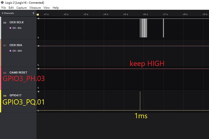
I see GPIO3_PH.03(cam0_rst) keep HIGH, and I sure that no other module control it.
I see GPIO3_PQ.01(GPIO17) low cycle is 1ms.

4.I control GPIO3_PH.03(cam0_rst) and GPIO3_PQ.01(GPIO17), and do gpio TEST2.
initial GPIO3_PH.03(cam0_rst) to GPIOF_OUT_INIT_HIGH
initial GPIO3_PQ.01(GPIO17) to GPIOF_OUT_INIT_LOW
GPIO3_PH.03(cam0_rst) set LOW
GPIO3_PQ.01(GPIO17) set to LOW
mdealy(1)
GPIO3_PH.03(cam0_rst) set HIGH
GPIO3_PQ.01(GPIO17) set to HIGH

define MY_GPIO17 417 //GPIO3_PQ.01
define MY_CAM0_RST 0x15B //GPIO3_PH.03

err = devm_gpio_request_one(&client->dev, MY_CAM0_RST, GPIOF_OUT_INIT_HIGH, “lt6911uxc-reset”);
if (err)
{
dev_err(&client->dev, “Failed to request Reset CAM_RST GPIO 0x%04X: %d\n”,MY_CAM0_RST, err);
return err;
}

err = devm_gpio_request_one(&client->dev, MY_GPIO17, GPIOF_OUT_INIT_LOW, “lt6911uxc-gpio417”);
if (err)
{
dev_err(&client->dev, “Failed to request GPIO 0x%04X: %d\n”,MY_GPIO17, err);
return err;
}

gpio_set_value(MY_CAM0_RST, 0);
dev_info(&client->dev, “CAM0_RST Reset (gpio 0x%04X) to low\n”, MY_CAM0_RST);

gpio_set_value(MY_GPIO17, 1);
dev_info(&client->dev, “(lt6911uxc-gpio417 (gpio 0x%04X) to high\n”, MY_GPIO17);

mdelay(1);

gpio_set_value(MY_CAM0_RST, 1);
dev_info(&client->dev, “CAM0_RST Reset (gpio 0x%04X) to high\n”, MY_CAM0_RST);

gpio_set_value(MY_GPIO17, 0);
dev_info(&client->dev, “(lt6911uxc-gpio417 (gpio 0x%04X) to low\n”, MY_GPIO17);

I see GPIO3_PH.03(cam0_rst) high cycle is 548ms.
I see GPIO3_PQ.01(GPIO17) low cycle is 1ms.

My question is why I control GPIO3_PQ.01(GPIO17) is working fine for 1ms, but GPIO3_PH.03(cam0_rst) is 548ms?

hello SammyChenTw,

ahh… there’s linux level offsets, 288
for example,

[    0.880106] gpiochip_setup_dev: registered GPIOs 288 to 511 on device: gpiochip0 (tegra-gpio)

this offset need to considered if you check the pin after it boot into linux kernel.
so… 0x3B + 288d = 0x15B

hello SammyChenTw

could you please try below to improve GPIO performance.
for example,

# cd  /sys/kernel/debug/bpmp/debug/clk/axi_cbb
# echo max_rate > rate
# echo 1 > mrq_rate_locked

I get write error when echo max_rate to rate:

# cd  /sys/kernel/debug/bpmp/debug/clk/axi_cbb
#echo max_rate > rate
bash: echo: write error: Input/output error

So I try cat max_rate to rat and echo 1 to mrq_rate_locked

# cd  /sys/kernel/debug/bpmp/debug/clk/axi_cbb
# cat max_rate
408000000
# cat max_rate > rate
# cat rate
408000000
# echo 1 > mrq_rate_locked

But GPIO3_PH.03(cam0_rst) is same 548ms, and GPIO performance seem donen’t improve.

I see the signal name and ball name of pin L5 are UART4_TX, and pin muxing only GPIO3_PH.03 in Jetson_AGX_Series_DevKit_Pinmux_Configuration_Template.xlsm.
How to verfy the pinctrl setting is GPIO3_PH.03?

hello SammyChenTw,

the pins that are associated with SoC straps, BOOT_SEL1 strap.
please also check [15.3 Strapping Pins] from Jetson AGX Xavier Series OEM Product Design Guide.

Strapping pins only use for force recovery mode in during power on.
What’s setting that I need to check?

hello SammyChenTw,

I’m wondering if you define the pin as decimal will change anything?
i.e. MY_CAM0_RST 347

I had try MY_CAM0_RST from 0x15B to 347, and result is same 548ms, and no change anything.
#define MY_GPIO17 417
#define MY_CAM0_RST 347

I check the pinmux-pins, and pin59 is tegra-gpio.347, and pin129 is tegra-gpio417.
The two pins are all gpio.
/sys/kernel/debug/pinctrl/2430000.pinmux/pinmux-pins

pin 59 (UART4_TX_PH3): (MUX UNCLAIMED) tegra-gpio:347
pin 129 (SOC_GPIO21_PQ1): (MUX UNCLAIMED) tegra-gpio:417

hello SammyChenTw,

instead of GPIO3_PH.03, I’ve see internal reference driver using GPIO3_PH.04 as reset-gpios.
the toggle time of gpio348 active normally in our test results. (~1ms)
we may need to narrow down the issue, could you please also try with gpio348 to have confirmation,
thanks

But I can’t see the GPIO3_PH.04 in pinmux table?
Is GPIO3_PH.04 the pin# L48 ?

I see the pin L48 in schematic, and it pull down 10K omh to GND.

hello SammyChenTw,

so far we don’t have platform to repo this, we’ve test on reference platforms (older AGX Xavier) that’s including plugin-manger to overwrite the CAM0_RST with GPIO3_PH.04.
did you see such 548ms to toggle GPIO3_PH.03 within the kernel driver side? do you have other camera module to test this behavior?

I test GPIO3_PH.04 and GPIO3_PQ.01 in ov5693.c on Xavier EVB+OV5693 sensor.
I control GPIO3_PQ.01 with1ms delay in ov5693_probe(), and scope can see 1ms plus.
I control GPIO3_PH.04 with1ms delay in ov5693_probe(), but scope see 19ms plus.