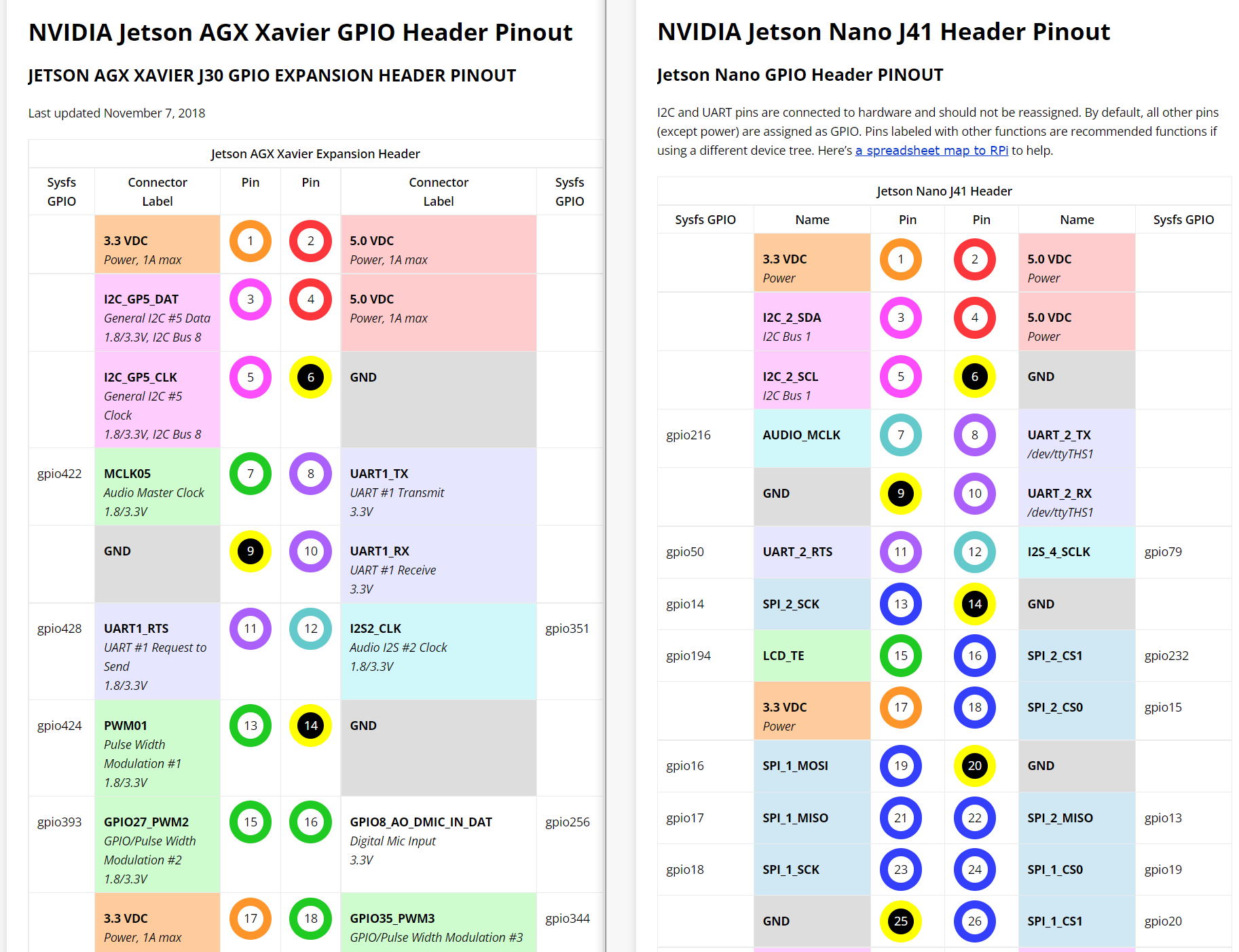
On the AGX Xavier some of the pins, which have the option of being used as gpio or pwm, (such as pin15) show the voltage as 1.8V/3.3V. Pin 37 is a gpio pin that shows 3.3V only.
Can I toggle this 1.8V mode to a 3.3V mode? I have not been able to use these pin for anything. I have tried using pin 15 as a gpio pin. I get nothing out of it. I have tried using pin 15 as a pwm pin after setting it to pwn with sudo /opt/nvidia/jetson-io/jetson-io.py . I get no signal out of it. I connect an electrometer to the pin during the attempt at gpio and during the attempt at pwm. I get no change in voltage out of it. The voltage seems to be at 0.1V or 0.3V with no changes.
When I set pin 15 to pwm and run a program that is supposed to send a pwm signal through pin 15 I expect it to move the motor and to have a specific signal of voltage out of the pin when I touch the electrometer to the pin.
import RPi.GPIO as GPIO   # Import the GPIO library.
import time               # Import time library
GPIO.setmode(GPIO.BOARD)  # Set Pi to use pin number when referencing GPIO pins.
                          # Can use GPIO.setmode(GPIO.BCM) instead to use
                          # Broadcom SOC channel names.
GPIO.setup(15, GPIO.OUT)  # Set GPIO pin 12 to output mode.
pwm = GPIO.PWM(15, 100)   # Initialize PWM on pwmPin 100Hz frequency
# main loop of program
print("\nPress Ctl C to quit \n")  # Print blank line before and after message.
dc=0                               # set dc variable to 0 for 0%
pwm.start(dc)                      # Start PWM with 0% duty cycle

try:
  while True:                      # Loop until Ctl C is pressed to stop.
    for dc in range(0, 101, 5):    # Loop 0 to 100 stepping dc by 5 each loop
      pwm.ChangeDutyCycle(dc)
      time.sleep(0.05)             # wait .05 seconds at current LED brightness
      print(dc)
    for dc in range(95, 0, -5):    # Loop 95 to 5 stepping dc down by 5 each loop
      pwm.ChangeDutyCycle(dc)
      time.sleep(0.05)             # wait .05 seconds at current LED brightness
      print(dc)
except KeyboardInterrupt:
  print("Ctl C pressed - ending program")
pwm.stop()                         # stop PWM
GPIO.cleanup()                     # resets GPIO ports used back to input mode
I tried the solution to a similar question here. It leads to a pdf which says “$ cat /proc/device-tree/nvidia,dtsfilename
If the file name is tegra210-p3448-0000-p3449-0000-a02.dts, the version is a02. If it is
tegra210-p3448-0000-p3449-0000-b00.dts, the version is b00.”
When I typed $ cat /proc/device-tree/nvidia,dtsfilename
I got
/dvs/git/dirty/git-master_linux/kernel/kernel-4.9/arch/arm64/boot/dts/../../../../../../hardware/nvidia/platform/t19x/galen/kernel-dts/common/tegra194-p2888-0001-p2822-0000-common.dtsi