CAN from SPE

Hi!

I’m looking for some guidance on how to correctly enable the required clocks for running the CAN block from the SPE. I’ve had some success but I don’t think I’m quite there yet.

So let’s begin with what I have so far.

I’ve modified the firewall to allow the SPE to control the relevant registers in the CAR.

        reg@2125 { /* CAR, CLK_RST_CONTROLLER_AON_SCR_CAN_0 */
            exclusion-info = <3>;
            value = <0x30001410>;
        };

I’m then setting up, what i think is the CAN1 core-clock, from the SPE with the same values as the BPMP writes when running the regular Linux kernel module. (figured by just reading back these registers after the ttcan kernel module has been inserted). 0xb10000 comes from arclk_rst.h in the SPE firmware repo.

  reg_wr(0x20b11000, 3); // CAN1_CLK_OUT ?
  reg_wr(0x20b13000, 2); // CAN1_CLK_SRC ?

I can then make the CAN block drop out of reset with:

  reg_wr(0x20b10000, 0);

I’m also setting COK in the M_TTCAN_CONTROL_REGISTER0_0

After this I can read/write to the CAN registers but the CAN bus-status stays in synchronizing state and it keeps complaining about various errors and also the read-error-counter keeps increasing and pegs to 127.
I’m also writing the exact same value (0x0000230c) as the kernel module in the NBTP register.
I’ve only tried receiving frames so far, not transmitted. But it seems like the clocks are not configured correctly.

The BPMP and TRM mentions three (different ?) clocks:

/** @brief output of mux controlled by CLK_RST_CONTROLLER_CLK_SOURCE_CAN1 */
#define TEGRA234_CLK_CAN1			9U
/** @brief output of gate CLK_ENB_CAN1_HOST */
#define TEGRA234_CLK_CAN1_HOST			10U
/** @brief CLK_RST_CONTROLLER_CAN1_CORE_RATE divider output */
#define TEGRA234_CLK_CAN1_CORE			284U

and (TRM chapter 9.4.2.1.1)

The following table has the frequency ranges for CAN.
Clock                               Minimum       Maximum
CCLK                                8 MHz         80 MHz
HCLK (always N*CCLK, N=1,2,3,4)     8 MHz         320 MHz
PCLK (System Dependent)             N/A           N/A

Are all these configured from the CAR 0x20b1xxxx register section or am I missing something here?

I’ve made sure the ttcan kernel module is not loaded and the relevant can sections are set to disabled in the kernel/bootloader device-tree. (I’ve also tried without booting Linux at all, same results)

Any advice would be much appreciated.
Thanks.
Hi andreas6,

Are you using the devkit or custom board for Orin Nano?
What’s the Jetpack version in use?

How do you find that there’s CAN interface from SPE?

Please refer to Jetson Sensor Processing Engine (SPE) Developer Guide: Welcome for SPE on Orin Nano.

May I know what’s your use case and requirement?

This is a custom carrier board, jetpack version is 36.4.3

The TRM says so in Chapter 8.9.1:

The AON cluster provides a processor (the SPE) and a set of peripherals in a small power island that
may remain on when the majority of the System-on-Chip (SoC) is powered off. This cluster
supports some I/O functions, and also provides hardware to wake the SoC when a number of
different events occur.
Use cases include, but are not limited to:
 * low power sensor management during standby
 * running specific communications stacks in standby, including the CAN bus
 * wake management from sleep states

Also the fact that there are directly routed IRQ from the CAN blocks to the SPE’s AVIC0 would indicate this is in fact an intended usecase.

Yes, but the SPE firmware offered by Nvidia does not have CAN support, this is what i’m trying to add.

Also see this thread: How can I use the SPE & CAN and Where I get the SCR info? - #4 by jachen

I would like to run custom code in the SPE and control peripherals over CAN, SPI and GPIO with better realtime performance that what Linux can offer.

I’m also interested in low-power-mode and wakeup over CAN.

As the TRM indicates this is the intended use for the SPE and AON cluster.

Thanks.

Can you refer to Controller Area Network (CAN) — NVIDIA Jetson Linux Developer Guide and use internal mttcan instead?
It seems they are also from AON cluster. (PAA.00/PAA.01).

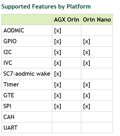
In the following table of current SPE document, it seems we don’t support for using CAN through SPE firmware.

As the thread you linked, maybe you have to implement them manually.

Yes. This is what I’ trying to do, but the Technical Reference Manual does not document how to setup the clocks as the CAR block is not documented.

I was hoping to get the support mentioned by Jachen from the referenced thread.

Hi andreas6,

I’ve found the following document from old release with CAN support in SPE.
Jetson Sensor Processing Engine (SPE) Developer Guide: CAN Application (app/can-app.c)

It seems we’ve removed it in current release for Orin series.
You can try to implement it manually but we don’t support for this use case and have not verified it on Orin currently.

Hello, andreas6:
yes, as Kevin stated, the CAN in Orin SPE is not supported so far.
Anyway, I think it’s still possible to implement that by yourself.

CAN-SPE can work in old BSP/SOC (rel-32/Xavier/Parker). You can take that code as reference.
If you get any problem, feel free to paste the code clip and logs here, and we can provide some suggestions.

Generally, you can do that step by step.

  1. Make sure that the SPE can access corresponding CAN module registers correctly. (Note, only CAN in AON cluster is accessible.)
  2. Inter-connect with CAN transceiver to do a test.
  3. Check waveforms for data transfer/clock setting.

Hope that can work in your side.

br
ChenJian

1 Like

I’ve everything working now. Just writing down my findings for anyone else who might be interested.

BPMP will initialize and enable the CAN clocks (HCLK 200MHz and CCLK 50MHz) except for not enabling the CAN core clock.
To do so set bit 4 in CLK_RST_CONTROLLER_CAN1_CORE_RATE_0 (0xb13004).

Then you need to release reset for the CAN block. Write 0 to CLK_RST_CONTROLLER_RST_DEV_CAN1_0 (0xb10000). Note that immediately after the SPE is released out of reset the clock-tree is not fully configured so you need to “wait a bit” until the CAN-block can be released out of reset. I’m currently just waiting 250ms. Not sure if there’s a better way to figure this out.

Finally set the COK bit in M_TTCAN_CONTROL_REGISTER0_0 (0x0c311014).

At this point the CAN block is up an running and I’m use the same standard Bosch TTCAN driver I’m using on STM32H7, STM32G4, etc.

Finally, after the Linux kernel has booted it will disable the CAN-clock from clk_disable_unused()as they are unused. I’m not sure what the best way around this is, but my current workaround is just to pass clk_ignore_unused to the kernel cmdline.

1 Like

For this, you can simply remove can0 clock configuration from lateinit to init in BPMP-DTB to prevent it disabled by clk_disable_unused().

FWIW, this doesn’t really work. (First of all can0 doesn’t exist, I assume you mean can1)

But there are still a few clocks disabled by the kernel.

TEGRA234_CLK_CAN1_HOST (10)

and

TEGRA234_CLK_CAN1_CORE (284)

They are not listed in the BPMP-DTS AFAICT.

Is it possible to just add those as well to the init -section, and if so, what should the parameters be?

Thanks

Yes, it should be can1 in bpmp-dtb.

Please try adding the following line in the init section of bpmp-dtb (tegra234-bpmp-3767-0000-a02-3509-a02.dtb)

                       can1 = <0x9 0x5e 0x0 0x0>;

This topic was automatically closed 14 days after the last reply. New replies are no longer allowed.