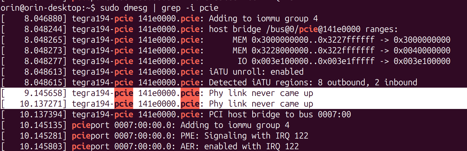
We have a custom board that we are using the Jetson Orin Nano on. We are trying to get an SSD to detect on the Orin, but having no luck. I believe the issue comes down to the pcie controller not being enabled - we want PCIE2 up, but it is not coming up.
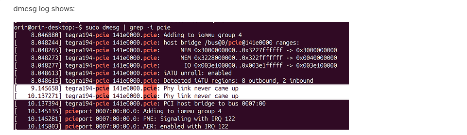
dmesg log shows:
which seems to indicate that the controller is not coming up. My gut tells me that this is something we can fix by changing the DTB, but I don’t have any experience working with them, so some guidance or resources would be appreciated. Attached is a boot log + some commands we tried.
June 9 SSD Debug Log.txt (56.4 KB)
Hi,
Just to clarify. If your so-called PCIE2 the default PCIe C7 x2 setting or you changed it to C7x1 and C9x1?
Or you totally don’t know what I am talkinga bout here?
I am still getting up to speed on this project, so apologies for the lack of info. Looking back at the documentation (this page, correct?), I think we actually want to bring up PCIe C1 - pcie@14100000. However, I assume whatever procedure/fix can be applied to each controller if this one does not work.
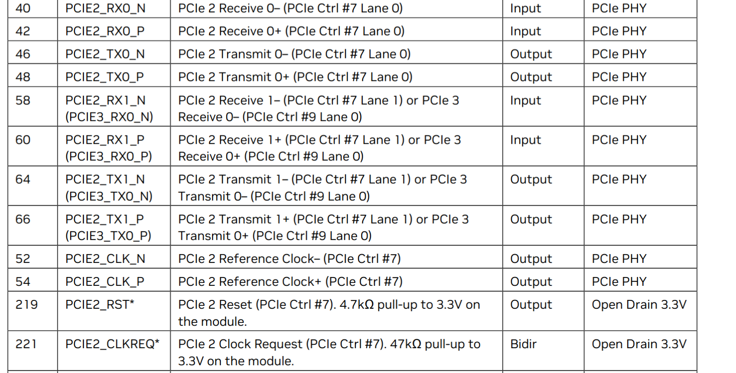
edit: checked the spec sheet, and I see where PCIe2 came from. We are connecting physically to the PCIE2 pins as referenced in the Jetson Orin Nano Series Modules Data Sheet.
so I guess ultimately what I am asking, is how to turn on these controllers from the software/DT side of things, and where to look to verify they are active.
It sounds like you don’t get the situation here.
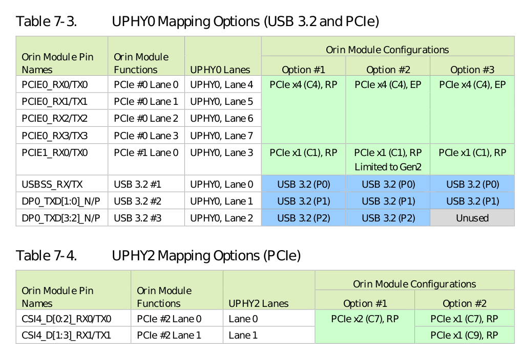
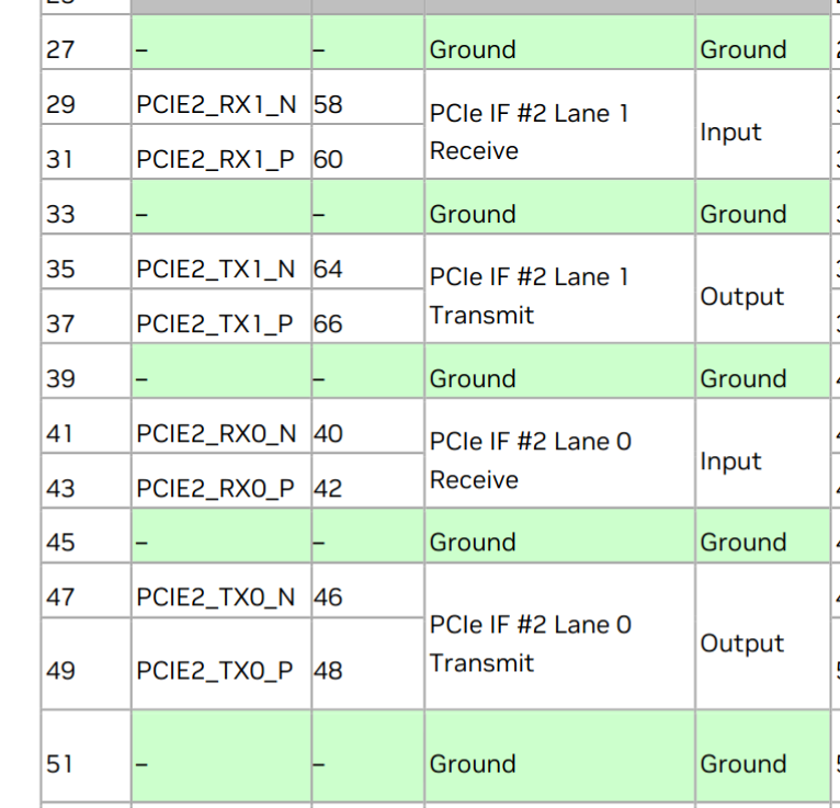
Your are not using C1. The screenshot you shared for PCIe2 is either C7 or C9…
Also, C7 is already enabled in default software. Only C9 needs to be enabled with extra software configuraiton.
So back to my question, do you use one PCIe device to occupy both lane 0 and lane1 here or you just want a x1 configuration.
Ah, I think I understand it now. Physical lanes “PCIE2” (pins 40-66ish) correspond to either Controller 7 or Controllers 7 and 9. There is a configuration option that allows to select which. In the device tree, these controllers are referenced as pcie@141e0000 for controller 7, and pcie@141c0000 for controller 9.
The device is an SSD, which actually appears to be configured as a 4x device (not possible with this PCIe interface, I know). However, it works on a dev kit, so I guess we want to follow the configuration there. That config has the device occupying both lanes, right? From the Dev Kit Specs:
To be clear: from table 7-4 in your screenshot, we want to select Option #1.
We traced the pins and verified that everything is wired up correctly. Interestingly, we are sending a signal to pin 221, PCIE2_CLKREQ, but not getting any clock signals on 52 and 54, PCIE2_CLK_N and PCIE2_CLK_P respectively. Seems like that is the (or an) error that needs to be addressed. Is there a way to force the Orin to send a clock signal from the software side?
Just to clarify. Option #1 is already the default setting enabled in default device tree.
When you posted the first screenshot here. It means PCIe C7 (141e0000) is already enabled. Otherwise you won’t even see the print from 141e0000
The problem here is the link detection has failure. It is common when you made your own hardware or test a new PCIe device.
Below debug tips might help.