I need some help to preview my gmsl camera on xavier, jetson linux version 32.5.1.
i have set the max96712 as 2x4 mode. All 4 cameras signals are output to CSI-A and CSI-B (lane0-lane3) with virtual channel 0,1,2,3
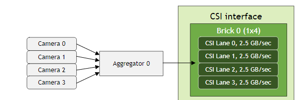
I only insert the first camera, and I can Detected mipi data in CSI-A and CSI-B (lane0-lane3). But I can’t preview the camera.
the preview command is:
gst-launch-1.0 v4l2src device=/dev/video0 ! ‘video/x-raw, format=UYVY, width=1920, height=1200, framerate=30/1’ ! xvimagesink -ev
Below is the error log:
dmesg.log (4.6 KB)
trace.log (34.4 KB)
I have referred to some other similar posts and made some changes to the DTS, but the issue has not been resolved yet.
I haven’t set a virtual channel before ,I don’t know where the problem is, please help me to solve the problem.thanks.
the dts:
/ {
	host1x {
		vi@15c10000 {
			num-channels = <4>;
			ports {
				#address-cells = <1>;
				#size-cells = <0>;
				port@0 {
					reg = <0>;
					ar0233_vi_in0: endpoint {
						vc-id = <0>;
						port-index = <0>;
						bus-width = <4>;
						remote-endpoint = <&ar0233_csi_out0>;
					};
				};
				port@1 {
					reg = <1>;
					ar0233_vi_in1: endpoint {
						vc-id = <1>;
						port-index = <0>;
						bus-width = <4>;
						remote-endpoint = <&ar0233_csi_out1>;
					};
				};
				port@2 {
					reg = <2>;
					ar0233_vi_in2: endpoint {
						vc-id = <2>;
						port-index = <0>;
						bus-width = <4>;
						remote-endpoint = <&ar0233_csi_out2>;
					};
				};
				port@3 {
					reg = <3>;
					ar0233_vi_in3: endpoint {
						vc-id = <3>;
						port-index = <0>;
						bus-width = <4>;
						remote-endpoint = <&ar0233_csi_out3>;
					};
				};
/*
				port@4 {
					reg = <4>;
					ar0233_vi_in4: endpoint {
						vc-id = <0>;
						port-index = <4>;
						bus-width = <2>;
						remote-endpoint = <&ar0233_csi_out4>;
					};
				};
				port@5 {
					reg = <5>;
					ar0233_vi_in5: endpoint {
						vc-id = <0>;
						port-index = <5>;
						bus-width = <2>;
						remote-endpoint = <&ar0233_csi_out5>;
					};
				};
*/
			};
		};

		nvcsi@15a00000 {
			num-channels = <4>;
			#address-cells = <1>;
			#size-cells = <0>;
			channel@0 {
				reg = <0>;
				ports {
					#address-cells = <1>;
					#size-cells = <0>;
					port@0 {
						reg = <0>;
						ar0233_csi_in0: endpoint@0 {
							port-index = <0>;
							bus-width = <4>;
							remote-endpoint = <&ar0233_ar0233_out0>;
						};
					};
					port@1 {
						reg = <1>;
						ar0233_csi_out0: endpoint@1 {
							remote-endpoint = <&ar0233_vi_in0>;
						};
					};
				};
			};
			channel@1 {
				reg = <1>;
				ports {
					#address-cells = <1>;
					#size-cells = <0>;
					port@0 {
						reg = <0>;
						ar0233_csi_in1: endpoint@2 {
							port-index = <0>;
							bus-width = <4>;
							remote-endpoint = <&ar0233_ar0233_out1>;
						};
					};
					port@1 {
						reg = <1>;
						ar0233_csi_out1: endpoint@3 {
							remote-endpoint = <&ar0233_vi_in1>;
						};
					};
				};
			};
			channel@2 {
				reg = <2>;
				ports {
					#address-cells = <1>;
					#size-cells = <0>;
					port@0 {
						reg = <0>;
						ar0233_csi_in2: endpoint@4 {
							port-index = <0>;
							bus-width = <4>;
							remote-endpoint = <&ar0233_ar0233_out2>;
						};
					};
					port@1 {
						reg = <1>;
						ar0233_csi_out2: endpoint@5 {
							remote-endpoint = <&ar0233_vi_in2>;
						};
					};
				};
			};
			channel@3 {
				reg = <3>;
				ports {
					#address-cells = <1>;
					#size-cells = <0>;
					port@0 {
						reg = <0>;
						ar0233_csi_in3: endpoint@6 {
							port-index = <0>;
							bus-width = <4>;
							remote-endpoint = <&ar0233_ar0233_out3>;
						};
					};
					port@1 {
						reg = <1>;
						ar0233_csi_out3: endpoint@7 {
							remote-endpoint = <&ar0233_vi_in3>;
						};
					};
				};
			};
		};
	};

	i2c@3180000 {
		imx390_a@1b {
				compatible = "nvidia,imx390";

				reg = <0x1b>;

				/* Physical dimensions of sensor */
				physical_w = "15.0";
				physical_h = "12.5";

				sensor_model ="imx390";

				/* Defines number of frames to be dropped by driver internally after applying */
				/* sensor crop settings. Some sensors send corrupt frames after applying */
				/* crop co-ordinates */
				post_crop_frame_drop = "0";

				/* Convert Gain to unit of dB (decibel) befor passing to kernel driver */
				use_decibel_gain = "true";

				/* enable CID_SENSOR_MODE_ID for sensor modes selection */
				use_sensor_mode_id = "true";

				/**
				* A modeX node is required to support v4l2 driver
				* implementation with NVIDIA camera software stack
				*
				* mclk_khz = "";
				* Standard MIPI driving clock, typically 24MHz
				*
				* num_lanes = "";
				* Number of lane channels sensor is programmed to output
				*
				* tegra_sinterface = "";
				* The base tegra serial interface lanes are connected to
				*
				* vc_id = "";
				* The virtual channel id of the sensor.
				*
				* discontinuous_clk = "";
				* The sensor is programmed to use a discontinuous clock on MIPI lanes
				*
				* dpcm_enable = "true";
				* The sensor is programmed to use a DPCM modes
				*
				* cil_settletime = "";
				* MIPI lane settle time value.
				* A "0" value attempts to autocalibrate based on mclk_khz and pix_clk_hz
				*
				* active_w = "";
				* Pixel active region width
				*
				* active_h = "";
				* Pixel active region height
				*
				* dynamic_pixel_bit_depth = "";
				* sensor dynamic bit depth for sensor mode
				*
				* csi_pixel_bit_depth = "";
				* sensor output bit depth for sensor mode
				*
				* mode_type="";
				* Sensor mode type, For eg: yuv, Rgb, bayer, bayer_wdr_pwl
				*
				* pixel_phase="";
				* Pixel phase for sensor mode, For eg: rggb, vyuy, rgb888
				*
				* readout_orientation = "0";
				* Based on camera module orientation.
				* Only change readout_orientation if you specifically
				* Program a different readout order for this mode
				*
				* line_length = "";
				* Pixel line length (width) for sensor mode.
				* This is used to calibrate features in our camera stack.
				*
				* pix_clk_hz = "";
				* Sensor pixel clock used for calculations like exposure and framerate
				*
				*
				*
				*
				* inherent_gain = "";
				* Gain obtained inherently from mode (ie. pixel binning)
				*
				* min_gain_val = ""; (floor to 6 decimal places)
				* max_gain_val = ""; (floor to 6 decimal places)
				* Gain limits for mode
				* if use_decibel_gain = "true", please set the gain as decibel
				*
				* min_exp_time = ""; (ceil to integer)
				* max_exp_time = ""; (ceil to integer)
				* Exposure Time limits for mode (us)
				*
				*
				* min_hdr_ratio = "";
				* max_hdr_ratio = "";
				* HDR Ratio limits for mode
				*
				* min_framerate = "";
				* max_framerate = "";
				* Framerate limits for mode (fps)
				*
				* embedded_metadata_height = "";
				* Sensor embedded metadata height in units of rows.
				* If sensor does not support embedded metadata value should be 0.
				*/

				mode0 {/*mode IMX390_MODE_1920X1080_CROP_30FPS*/
					mclk_khz = "24000";
					num_lanes = "4";
					tegra_sinterface = "serial_a";
					vc_id = "0";
					discontinuous_clk = "no";
					dpcm_enable = "false";
					cil_settletime = "0";
					dynamic_pixel_bit_depth = "16";
					csi_pixel_bit_depth = "16";
					mode_type = "yuv";
					pixel_phase = "uyvy";

					active_w = "1920";
					active_h = "1200";
					readout_orientation = "0";
					line_length = "1920";
					inherent_gain = "1";
					pix_clk_hz = "350000000";
					serdes_pix_clk_hz = "350000000";

					gain_factor = "10";
					min_gain_val = "0"; /* dB */
					max_gain_val = "300"; /* dB */
					step_gain_val = "3"; /* 0.3 */
					default_gain = "0";
					min_hdr_ratio = "1";
					max_hdr_ratio = "1";
					framerate_factor = "1";
					min_framerate = "1";
					max_framerate = "30";
					step_framerate = "1";
					default_framerate = "30";
					exposure_factor = "1000000";
					min_exp_time = "59"; /*us, 2 lines*/
					max_exp_time = "33333";
					step_exp_time = "1";
					default_exp_time = "33333";/* us */
					embedded_metadata_height = "0";
				};
				ports {
					#address-cells = <1>;
					#size-cells = <0>;
					port@0 {
						reg = <0>;
						ar0233_ar0233_out0: endpoint {
							vc-id = <0>;
							port-index = <0>;
							bus-width = <4>;
							remote-endpoint = <&ar0233_csi_in0>;
							};
						};
					};
				gmsl-link {
					src-csi-port = "a";
					dst-csi-port = "a";
					serdes-csi-link = "a";
					csi-mode = "1x4";
					st-vc = <0>;
					vc-id = <0>;
					num-lanes = <4>;
					streams = "ued-u1", "raw12";
					};
		};

		imx390_b@1c {
				compatible = "nvidia,imx390";

				reg = <0x1c>;

				/* Physical dimensions of sensor */
				physical_w = "15.0";
				physical_h = "12.5";

				sensor_model ="imx390";

				/* Defines number of frames to be dropped by driver internally after applying */
				/* sensor crop settings. Some sensors send corrupt frames after applying */
				/* crop co-ordinates */
				post_crop_frame_drop = "0";

				/* Convert Gain to unit of dB (decibel) befor passing to kernel driver */
				use_decibel_gain = "true";

				/* enable CID_SENSOR_MODE_ID for sensor modes selection */
				use_sensor_mode_id = "true";

				/**
				* A modeX node is required to support v4l2 driver
				* implementation with NVIDIA camera software stack
				*
				* mclk_khz = "";
				* Standard MIPI driving clock, typically 24MHz
				*
				* num_lanes = "";
				* Number of lane channels sensor is programmed to output
				*
				* tegra_sinterface = "";
				* The base tegra serial interface lanes are connected to
				*
				* vc_id = "";
				* The virtual channel id of the sensor.
				*
				* discontinuous_clk = "";
				* The sensor is programmed to use a discontinuous clock on MIPI lanes
				*
				* dpcm_enable = "true";
				* The sensor is programmed to use a DPCM modes
				*
				* cil_settletime = "";
				* MIPI lane settle time value.
				* A "0" value attempts to autocalibrate based on mclk_khz and pix_clk_hz
				*
				* active_w = "";
				* Pixel active region width
				*
				* active_h = "";
				* Pixel active region height
				*
				* dynamic_pixel_bit_depth = "";
				* sensor dynamic bit depth for sensor mode
				*
				* csi_pixel_bit_depth = "";
				* sensor output bit depth for sensor mode
				*
				* mode_type="";
				* Sensor mode type, For eg: yuv, Rgb, bayer, bayer_wdr_pwl
				*
				* pixel_phase="";
				* Pixel phase for sensor mode, For eg: rggb, vyuy, rgb888
				*
				* readout_orientation = "0";
				* Based on camera module orientation.
				* Only change readout_orientation if you specifically
				* Program a different readout order for this mode
				*
				* line_length = "";
				* Pixel line length (width) for sensor mode.
				* This is used to calibrate features in our camera stack.
				*
				* pix_clk_hz = "";
				* Sensor pixel clock used for calculations like exposure and framerate
				*
				*
				*
				*
				* inherent_gain = "";
				* Gain obtained inherently from mode (ie. pixel binning)
				*
				* min_gain_val = ""; (floor to 6 decimal places)
				* max_gain_val = ""; (floor to 6 decimal places)
				* Gain limits for mode
				* if use_decibel_gain = "true", please set the gain as decibel
				*
				* min_exp_time = ""; (ceil to integer)
				* max_exp_time = ""; (ceil to integer)
				* Exposure Time limits for mode (us)
				*
				*
				* min_hdr_ratio = "";
				* max_hdr_ratio = "";
				* HDR Ratio limits for mode
				*
				* min_framerate = "";
				* max_framerate = "";
				* Framerate limits for mode (fps)
				*
				* embedded_metadata_height = "";
				* Sensor embedded metadata height in units of rows.
				* If sensor does not support embedded metadata value should be 0.
				*/

				mode0 {/*mode IMX390_MODE_1920X1080_CROP_30FPS*/
					mclk_khz = "24000";
					num_lanes = "4";
					tegra_sinterface = "serial_b";
					vc_id = "1";
					discontinuous_clk = "no";
					dpcm_enable = "false";
					cil_settletime = "0";
					dynamic_pixel_bit_depth = "16";
					csi_pixel_bit_depth = "16";
					mode_type = "yuv";
					pixel_phase = "uyvy";

					active_w = "1920";
					active_h = "1200";
					readout_orientation = "0";
					line_length = "1920";
					inherent_gain = "1";
					pix_clk_hz = "87500000";
					serdes_pix_clk_hz = "350000000";

					gain_factor = "10";
					min_gain_val = "0"; /* dB */
					max_gain_val = "300"; /* dB */
					step_gain_val = "3"; /* 0.3 */
					default_gain = "0";
					min_hdr_ratio = "1";
					max_hdr_ratio = "1";
					framerate_factor = "1";
					min_framerate = "1";
					max_framerate = "30";
					step_framerate = "1";
					default_framerate = "30";
					exposure_factor = "1000000";
					min_exp_time = "59"; /*us, 2 lines*/
					max_exp_time = "33333";
					step_exp_time = "1";
					default_exp_time = "33333";/* us */
					embedded_metadata_height = "0";
				};
				ports {
					#address-cells = <1>;
					#size-cells = <0>;
					port@0 {
						reg = <0>;
						ar0233_ar0233_out1: endpoint {
							vc-id = <1>;
							port-index = <0>;
							bus-width = <4>;
							remote-endpoint = <&ar0233_csi_in1>;
							};
						};
					};
				gmsl-link {
					src-csi-port = "b";
					dst-csi-port = "a";
					serdes-csi-link = "a";
					csi-mode = "1x4";
					st-vc = <0>;
					vc-id = <1>;
					num-lanes = <4>;
					streams = "ued-u1", "raw12";
					};
				};

		imx390_c@1d {
				compatible = "nvidia,imx390";

				reg = <0x1d>;

				/* Physical dimensions of sensor */
				physical_w = "15.0";
				physical_h = "12.5";

				sensor_model ="imx390";

				/* Defines number of frames to be dropped by driver internally after applying */
				/* sensor crop settings. Some sensors send corrupt frames after applying */
				/* crop co-ordinates */
				post_crop_frame_drop = "0";

				/* Convert Gain to unit of dB (decibel) befor passing to kernel driver */
				use_decibel_gain = "true";

				/* enable CID_SENSOR_MODE_ID for sensor modes selection */
				use_sensor_mode_id = "true";

				/**
				* A modeX node is required to support v4l2 driver
				* implementation with NVIDIA camera software stack
				*
				* mclk_khz = "";
				* Standard MIPI driving clock, typically 24MHz
				*
				* num_lanes = "";
				* Number of lane channels sensor is programmed to output
				*
				* tegra_sinterface = "";
				* The base tegra serial interface lanes are connected to
				*
				* vc_id = "";
				* The virtual channel id of the sensor.
				*
				* discontinuous_clk = "";
				* The sensor is programmed to use a discontinuous clock on MIPI lanes
				*
				* dpcm_enable = "true";
				* The sensor is programmed to use a DPCM modes
				*
				* cil_settletime = "";
				* MIPI lane settle time value.
				* A "0" value attempts to autocalibrate based on mclk_khz and pix_clk_hz
				*
				* active_w = "";
				* Pixel active region width
				*
				* active_h = "";
				* Pixel active region height
				*
				* dynamic_pixel_bit_depth = "";
				* sensor dynamic bit depth for sensor mode
				*
				* csi_pixel_bit_depth = "";
				* sensor output bit depth for sensor mode
				*
				* mode_type="";
				* Sensor mode type, For eg: yuv, Rgb, bayer, bayer_wdr_pwl
				*
				* pixel_phase="";
				* Pixel phase for sensor mode, For eg: rggb, vyuy, rgb888
				*
				* readout_orientation = "0";
				* Based on camera module orientation.
				* Only change readout_orientation if you specifically
				* Program a different readout order for this mode
				*
				* line_length = "";
				* Pixel line length (width) for sensor mode.
				* This is used to calibrate features in our camera stack.
				*
				* pix_clk_hz = "";
				* Sensor pixel clock used for calculations like exposure and framerate
				*
				*
				*
				*
				* inherent_gain = "";
				* Gain obtained inherently from mode (ie. pixel binning)
				*
				* min_gain_val = ""; (floor to 6 decimal places)
				* max_gain_val = ""; (floor to 6 decimal places)
				* Gain limits for mode
				* if use_decibel_gain = "true", please set the gain as decibel
				*
				* min_exp_time = ""; (ceil to integer)
				* max_exp_time = ""; (ceil to integer)
				* Exposure Time limits for mode (us)
				*
				*
				* min_hdr_ratio = "";
				* max_hdr_ratio = "";
				* HDR Ratio limits for mode
				*
				* min_framerate = "";
				* max_framerate = "";
				* Framerate limits for mode (fps)
				*
				* embedded_metadata_height = "";
				* Sensor embedded metadata height in units of rows.
				* If sensor does not support embedded metadata value should be 0.
				*/

				mode0 {/*mode IMX390_MODE_1920X1080_CROP_30FPS*/
					mclk_khz = "24000";
					num_lanes = "4";
					tegra_sinterface = "serial_c";
					vc_id = "2";
					discontinuous_clk = "no";
					dpcm_enable = "false";
					cil_settletime = "0";
					dynamic_pixel_bit_depth = "16";
					csi_pixel_bit_depth = "16";
					mode_type = "yuv";
					pixel_phase = "uyvy";

					active_w = "1920";
					active_h = "1200";
					readout_orientation = "0";
					line_length = "1920";
					inherent_gain = "1";
					pix_clk_hz = "87500000";
					serdes_pix_clk_hz = "350000000";

					gain_factor = "10";
					min_gain_val = "0"; /* dB */
					max_gain_val = "300"; /* dB */
					step_gain_val = "3"; /* 0.3 */
					default_gain = "0";
					min_hdr_ratio = "1";
					max_hdr_ratio = "1";
					framerate_factor = "1";
					min_framerate = "1";
					max_framerate = "30";
					step_framerate = "1";
					default_framerate = "30";
					exposure_factor = "1000000";
					min_exp_time = "59"; /*us, 2 lines*/
					max_exp_time = "33333";
					step_exp_time = "1";
					default_exp_time = "33333";/* us */
					embedded_metadata_height = "0";
				};
				ports {
					#address-cells = <1>;
					#size-cells = <0>;
					port@0 {
						reg = <0>;
						ar0233_ar0233_out2: endpoint {
							vc-id = <2>;
							port-index = <0>;
							bus-width = <4>;
							remote-endpoint = <&ar0233_csi_in2>;
							};
						};
					};
				gmsl-link {
					src-csi-port = "c";
					dst-csi-port = "a";
					serdes-csi-link = "a";
					csi-mode = "1x4";
					st-vc = <0>;
					vc-id = <2>;
					num-lanes = <4>;
					streams = "ued-u1", "raw12";
					};
				};

		imx390_d@1e {
				compatible = "nvidia,imx390";

				reg = <0x1e>;

				/* Physical dimensions of sensor */
				physical_w = "15.0";
				physical_h = "12.5";

				sensor_model ="imx390";

				/* Defines number of frames to be dropped by driver internally after applying */
				/* sensor crop settings. Some sensors send corrupt frames after applying */
				/* crop co-ordinates */
				post_crop_frame_drop = "0";

				/* Convert Gain to unit of dB (decibel) befor passing to kernel driver */
				use_decibel_gain = "true";

				/* enable CID_SENSOR_MODE_ID for sensor modes selection */
				use_sensor_mode_id = "true";

				/**
				* A modeX node is required to support v4l2 driver
				* implementation with NVIDIA camera software stack
				*
				* mclk_khz = "";
				* Standard MIPI driving clock, typically 24MHz
				*
				* num_lanes = "";
				* Number of lane channels sensor is programmed to output
				*
				* tegra_sinterface = "";
				* The base tegra serial interface lanes are connected to
				*
				* vc_id = "";
				* The virtual channel id of the sensor.
				*
				* discontinuous_clk = "";
				* The sensor is programmed to use a discontinuous clock on MIPI lanes
				*
				* dpcm_enable = "true";
				* The sensor is programmed to use a DPCM modes
				*
				* cil_settletime = "";
				* MIPI lane settle time value.
				* A "0" value attempts to autocalibrate based on mclk_khz and pix_clk_hz
				*
				* active_w = "";
				* Pixel active region width
				*
				* active_h = "";
				* Pixel active region height
				*
				* dynamic_pixel_bit_depth = "";
				* sensor dynamic bit depth for sensor mode
				*
				* csi_pixel_bit_depth = "";
				* sensor output bit depth for sensor mode
				*
				* mode_type="";
				* Sensor mode type, For eg: yuv, Rgb, bayer, bayer_wdr_pwl
				*
				* pixel_phase="";
				* Pixel phase for sensor mode, For eg: rggb, vyuy, rgb888
				*
				* readout_orientation = "0";
				* Based on camera module orientation.
				* Only change readout_orientation if you specifically
				* Program a different readout order for this mode
				*
				* line_length = "";
				* Pixel line length (width) for sensor mode.
				* This is used to calibrate features in our camera stack.
				*
				* pix_clk_hz = "";
				* Sensor pixel clock used for calculations like exposure and framerate
				*
				*
				*
				*
				* inherent_gain = "";
				* Gain obtained inherently from mode (ie. pixel binning)
				*
				* min_gain_val = ""; (floor to 6 decimal places)
				* max_gain_val = ""; (floor to 6 decimal places)
				* Gain limits for mode
				* if use_decibel_gain = "true", please set the gain as decibel
				*
				* min_exp_time = ""; (ceil to integer)
				* max_exp_time = ""; (ceil to integer)
				* Exposure Time limits for mode (us)
				*
				*
				* min_hdr_ratio = "";
				* max_hdr_ratio = "";
				* HDR Ratio limits for mode
				*
				* min_framerate = "";
				* max_framerate = "";
				* Framerate limits for mode (fps)
				*
				* embedded_metadata_height = "";
				* Sensor embedded metadata height in units of rows.
				* If sensor does not support embedded metadata value should be 0.
				*/

				mode0 {/*mode IMX390_MODE_1920X1080_CROP_30FPS*/
					mclk_khz = "24000";
					num_lanes = "4";
					tegra_sinterface = "serial_d";
					vc_id = "3";
					discontinuous_clk = "no";
					dpcm_enable = "false";
					cil_settletime = "0";
					dynamic_pixel_bit_depth = "16";
					csi_pixel_bit_depth = "16";
					mode_type = "yuv";
					pixel_phase = "uyvy";

					active_w = "1920";
					active_h = "1200";
					readout_orientation = "0";
					line_length = "1920";
					inherent_gain = "1";
					pix_clk_hz = "87500000";
					serdes_pix_clk_hz = "350000000";

					gain_factor = "10";
					min_gain_val = "0"; /* dB */
					max_gain_val = "300"; /* dB */
					step_gain_val = "3"; /* 0.3 */
					default_gain = "0";
					min_hdr_ratio = "1";
					max_hdr_ratio = "1";
					framerate_factor = "1";
					min_framerate = "1";
					max_framerate = "30";
					step_framerate = "1";
					default_framerate = "30";
					exposure_factor = "1000000";
					min_exp_time = "59"; /*us, 2 lines*/
					max_exp_time = "33333";
					step_exp_time = "1";
					default_exp_time = "33333";/* us */
					embedded_metadata_height = "0";
				};
				ports {
					#address-cells = <1>;
					#size-cells = <0>;
					port@0 {
						reg = <0>;
						ar0233_ar0233_out3: endpoint {
							vc-id = <3>;
							port-index = <0>;
							bus-width = <4>;
							remote-endpoint = <&ar0233_csi_in3>;
							};
						};
					};
				gmsl-link {
					src-csi-port = "d";
					dst-csi-port = "a";
					serdes-csi-link = "a";
					csi-mode = "1x4";
					st-vc = <0>;
					vc-id = <3>;
					num-lanes = <4>;
					streams = "ued-u1", "raw12";
					};
				};

		};
};

/ {

	tegra-camera-platform {
		compatible = "nvidia, tegra-camera-platform";
		/**
		* Physical settings to calculate max ISO BW
		*
		* num_csi_lanes = <>;
		* Total number of CSI lanes when all cameras are active
		*
		* max_lane_speed = <>;
		* Max lane speed in Kbit/s
		*
		* min_bits_per_pixel = <>;
		* Min bits per pixel
		*
		* vi_peak_byte_per_pixel = <>;
		* Max byte per pixel for the VI ISO case
		*
		* vi_bw_margin_pct = <>;
		* Vi bandwidth margin in percentage
		*
		* max_pixel_rate = <>;
		* Max pixel rate in Kpixel/s for the ISP ISO case
		*
		* isp_peak_byte_per_pixel = <>;
		* Max byte per pixel for the ISP ISO case
		*
		* isp_bw_margin_pct = <>;
		* Isp bandwidth margin in percentage
		*/
		num_csi_lanes = <4>;
		max_lane_speed = <4000000>;
		min_bits_per_pixel = <10>;
		vi_peak_byte_per_pixel = <2>;
		vi_bw_margin_pct = <25>;
		isp_peak_byte_per_pixel = <5>;
		isp_bw_margin_pct = <25>;

		/**
		 * The general guideline for naming badge_info contains 3 parts, and is as follows,
		 * The first part is the camera_board_id for the module; if the module is in a FFD
		 * platform, then use the platform name for this part.
		 * The second part contains the position of the module, ex. "rear" or "front".
		 * The third part contains the last 6 characters of a part number which is found
		 * in the module's specsheet from the vender.
		 */
		modules {
			module0 {
				badge = "imx390_rear";
				position = "rear";
				orientation = "1";
				drivernode0 {
					/* Declare PCL support driver (classically known as guid)  */
					pcl_id = "v4l2_sensor";
					/* Driver v4l2 device name */
					devname = "imx390 30-001b";
					/* Declare the device-tree hierarchy to driver instance */
					proc-device-tree = "/proc/device-tree/i2c@3180000/imx390_a@1b";
				};
			};
			module1 {
				badge = "imx390_front";
				position = "front";
				orientation = "1";
				drivernode0 {
					/* Declare PCL support driver (classically known as guid)  */
					pcl_id = "v4l2_sensor";
					/* Driver v4l2 device name */
					devname = "imx390 30-001c";
					/* Declare the device-tree hierarchy to driver instance */
					proc-device-tree = "/proc/device-tree/i2c@3180000/imx390_b@1c";
				};
			};
			module2 {
				badge = "imx390_left";
				position = "left";
				orientation = "1";
				drivernode0 {
					/* Declare PCL support driver (classically known as guid)  */
					pcl_id = "v4l2_sensor";
					/* Driver v4l2 device name */
					devname = "imx390 30-001d";
					/* Declare the device-tree hierarchy to driver instance */
					proc-device-tree = "/proc/device-tree/i2c@3180000/imx390_c@1d";
				};
			};
			module3 {
				badge = "imx390_right";
				position = "right";
				orientation = "1";
				drivernode0 {
					/* Declare PCL support driver (classically known as guid)  */
					pcl_id = "v4l2_sensor";
					/* Driver v4l2 device name */
					devname = "imx390 30-001e";
					/* Declare the device-tree hierarchy to driver instance */
					proc-device-tree = "/proc/device-tree/i2c@3180000/imx390_d@1e";
				};
			};
		};
	};
};