Hi all,
from the previous mentioned posts i came to understand that to interface Jetson Nano CAN bus in production module, there need to be application of pinmux changes and update. From the manual and online jetson documentation i am facing lot of difficulty. can some one please tell a very step by step guide to interface MCP Can bus in Jetson Nano production module.
Thanks in advance
Hi
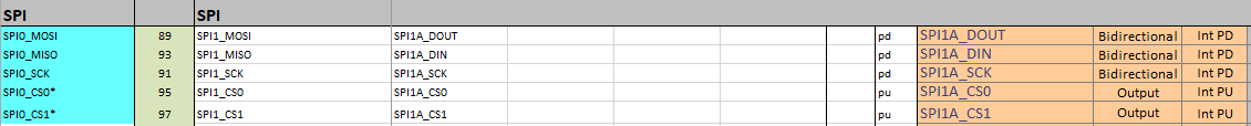
From the reference documentations i am trying to add spi 1 and spi2 into pinmux sheet with 2 gpio values(highlighted in yellow color in the second sheet). please refer to the screenshots of pinmux files and suggest if any changes required or not.
Thanks

hello philip.samuel,
had you refer to CanBus on the Nano - #33 by shgarg for Nano’s CAN communication?
Hi Jerry
Thanks
yes i have already referred to this post shared by shgarg. in that pinmux change is only mentioned. i have made changes to the pinmux sheet of jetson Som module emmc type.
-
can you please suggest if the parameters shown in the above image are correct or not?
-
Related to the post shared by shgarg should i make the dtb changes in the main nano kernel_tegra-p3448-0002-p3449-0000-b00.dtb file located in /boot/dtb folder.
Thanks for your reply
hello philip.samuel,
these two pins, GPIO07 and GPIO11 were default configured as GPIO.
you’ll see device tree definition as following,
for example,
        gpio: gpio@6000d000 {
                gpio-init-names = "default";
                gpio-init-0 = <&gpio_default>;

                gpio_default: default {
                        gpio-input = <
                                TEGRA_GPIO(V, 0)
                                TEGRA_GPIO(Z, 0)
please check the device tree blob you’re using. you may refer to kernel logs, $ dmesg | grep DTS.
and… you should have DTB update included for pin configurations.
This topic was automatically closed 14 days after the last reply. New replies are no longer allowed.