Hi NV Support Team
I want to use USB TypeA connector to flashing in my customer board.
From DG: The FORCE_RECOVERY_N strap is used to enter Force Recovery mode by holding it low during power-on.
That means if we hold FORCE_RECOVERY_N in low and Orin dont need check the USB ID pin status, The USB still working in Device mode. Is it correct ?
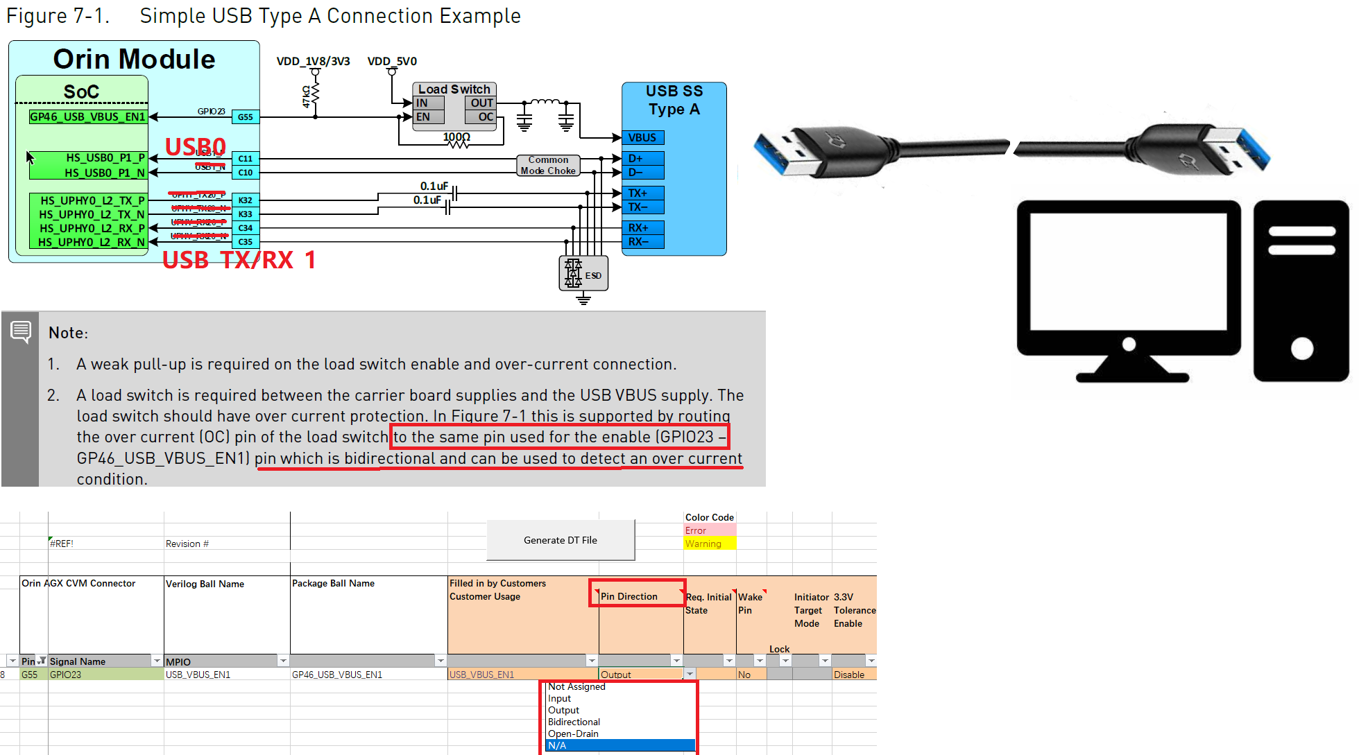
The VBUS_EN used as bidirection for OC and Enable load switch. That means we need config G55 (GPIO23) to bidirection in pinmux. Is it correct?
G55(GPIO23) voltage is 1.8V, The DG pull up to 3.3V, That means we need config 3.3V Tolerance Enable to Enable. Is it correct?
One more query about pin type from “Jetson_Orin_Pin_Description” document. many pin config as Opendrain.
That means we must to enable 3.3V tolerence in pinmux ?
That means if we hold FORCE_RECOVERY_N in low and Orin dont need check the USB ID pin status, The USB still working in Device mode. Is it correct ?
Yes, it’s correct.
The VBUS_EN used as bidirection for OC and Enable load switch. That means we need config G55 (GPIO23) to bidirection in pinmux. Is it correct?
Yes, it’s correct.
G55(GPIO23) voltage is 1.8V, The DG pull up to 3.3V, That means we need config 3.3V Tolerance Enable to Enable. Is it correct?
It’s PU to 1.8V or 3.3V. If 3.3V PU is used, ‘3.3V Tolerance Enable’ of GPIO23 need be configured as Enable.
One more query about pin type from “Jetson_Orin_Pin_Description” document. many pin config as Opendrain.
That means we must to enable 3.3V tolerence in pinmux ?
Not all pins can be configured as ‘3.3V Tolerance Enable’. It depends on your carrier board design. If 1.8V voltage level is used on the open-drain pin, it’s enough to set ‘3.3V Tolerance Enable’ to disable.