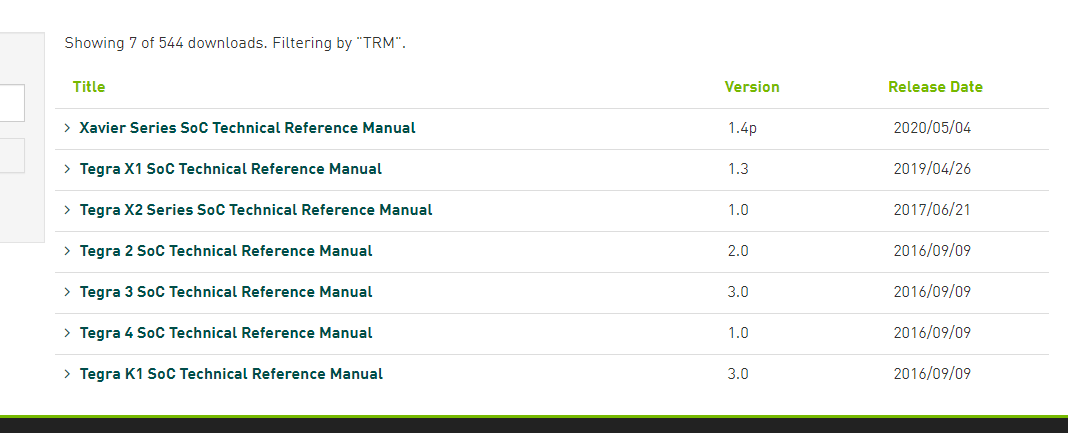
You can down the TRM from download center. Jetson Download Center | NVIDIA Developer
For the pixel clock it’s better to consult with sensor vendor.
And csi2_fops.c is for Nano/TX1 csi4_fops.c is for TX2
Check the TX1
hi shane, can i exec cmd to set/get register?
for example offset 0x250 byte offset 0x940

how can i read the register?
static u32 cil_read(struct tegra_csi_port *port, u32 addr)
What should be the value of this addr?
1.log (115.0 KB)
i run jetson-multimedia_api/09_camera_jpeg_capture sample, and can’t show the image.
You sensor still have output problem absolutely not working for any sample code.
Have a check sensor programing guide use v4l2-ctl to confirm the driver is working well first.
Also you can’t assess these REG from user space. You can read it from the csi2_fops.c
hi shane, I measured the data and clock lane, when I execute the sample, they all have signals.
You have to make sure the signal and power sequence match the MIPI spec.
hi shane, I don’t know which register in the code corresponds to the register in the document.
Which REG? Check previous comment and trace the csi2_fops.c
Below error tell the clock/data lane control error have a check the REG CSI_CSI_CILA_STATUS_0 and CSI_CSI_CIL_A_STATUS_0 from the TRM.
It could be the sensor with continous clock mode and enable sensor streaming before enable NVCSI.

[ 4901.856050] vi 54080000.vi: TEGRA_CSI_CILX_STATUS 0x00040041
hi shane,
how can i read CSI_CSI_CILA_STATUS_0?
What should be the value of this addr?
static u32 cil_read(struct tegra_csi_port *port, u32 addr)

The csi2_fops.c already read and print it when capture failed.
[ 4899.984503] vi 54080000.vi: TEGRA_CSI_PIXEL_PARSER_STATUS 0x00000000
[ 4899.984521] vi 54080000.vi: TEGRA_CSI_CIL_STATUS 0x00000010
[ 4899.984536] vi 54080000.vi: TEGRA_CSI_CILX_STATUS 0x00040041
but i can’t find TEGRA_CSI_CIL_STATUS and TEGRA_CSI_CILX_STATUS in TRM. So i don’t understand what each bit means.
hi shane, TEGRA_CSI_CIL_STATUS == CSI1_CSI_CILA_STATUS_0?
/ {
tcp: tegra-camera-platform {
compatible = “nvidia, tegra-camera-platform”;
	/**
	* Physical settings to calculate max ISO BW
	*
	* num_csi_lanes = <>;
	* Total number of CSI lanes when all cameras are active
	*
	* max_lane_speed = <>;
	* Max lane speed in Kbit/s
	*
	* min_bits_per_pixel = <>;
	* Min bits per pixel
	*
	* vi_peak_byte_per_pixel = <>;
	* Max byte per pixel for the VI ISO case
	*
	* vi_bw_margin_pct = <>;
	* Vi bandwidth margin in percentage
	*
	* max_pixel_rate = <>;
	* Max pixel rate in Kpixel/s for the ISP ISO case
	*
	* isp_peak_byte_per_pixel = <>;
	* Max byte per pixel for the ISP ISO case
	*
	* isp_bw_margin_pct = <>;
	* Isp bandwidth margin in percentage
	*/
	num_csi_lanes = <8>;
	max_lane_speed = <1500000>;
	min_bits_per_pixel = <10>;
	vi_peak_byte_per_pixel = <2>;
	vi_bw_margin_pct = <25>;
	max_pixel_rate = <240000>;
	isp_peak_byte_per_pixel = <5>;
	isp_bw_margin_pct = <25>;
hi shane, can you help me check the label?
there are 2 4-lane sensor.
TEGRA_CSI_CIL_STATUS = CSI_CSI_CIL_A_STATUS_0
TEGRA_CSI_CILX_STATUS = CSI_CSI_CILA_STATUS_0
What label want me to confirm?
hi shane,
num_csi_lanes = <8>;
max_lane_speed = <1500000>;
min_bits_per_pixel = <10>;
vi_peak_byte_per_pixel = <2>;
vi_bw_margin_pct = <25>;
max_pixel_rate = <240000>;
isp_peak_byte_per_pixel = <5>;
isp_bw_margin_pct = <25>;
I can’t find any problem for it.