Hi there! I have a Jetson Orin AGX (64GB) Developer kit. I would like to use it for an application where I need to read the two phases of an encoder pulse. Also I would like to use both the CAN controllers.
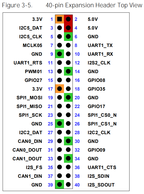
- In order to read the encoder pulses, I need the GPIO pins to be pulled down so that my I can read my high pulses from the encoder. I tried to use the pins 29,31 which are both PD internally (Checked it with a multimeter) and also works with my encoder, but pin 31 is mentioned as Int PU in the pinmux spreadsheet.
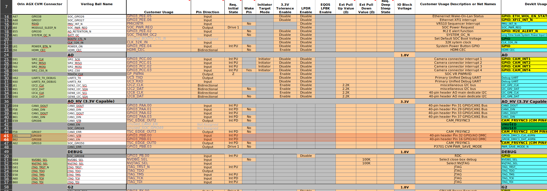
Also I don’t wanna use the CAN0 pins for this encoder application. So I wanted to use other GPIO pins that has internal PD. Are there any errors in the pinmux spreadsheet? Or am I doing something wrong here? Need help in changing the pinmux config of my GPIO pins. What other pins can be used for my requirement?
- Also while trying to understand the pinmux spreadsheet and my current pin configuration, I tried to used the pins 16,32 which are marked as DMIC input. where pin 32 is INT PU (I would like to change it to INT PD). which has the names 16 - GPIO3_PBB.01, 32 - GPIO3_PBB.00 which corresponds to the gpio numbers PBB.01 - gpio325, PBB.00 - gpio324

But the image from JetsonHacks marks pin 16 as gpio-357. Please clarify this, also I’m puzzled on how to understand how the gpio corresponds to the pin numbers in J30 header.