We have developed a custom carrier board with a few modifications to the Nvidia Carrier board system.
After I plug in the TX2 module flashed with Jetpack on my carrier board, the HDMI port works and I get a display but USB port does not work. USB_VBUS_EN1 is not pulled up to 3.3V. From what I gather taking some measurements on Development system, USB_VBUS_EN1 just goes to 3.3V after a set period of time with nothing connected on USB port to enable load switch for the port.
I even tried to tie the load switch EN to 5V for the port to receive power but my system doesnt recognize the devices. I am trying to plug in mouse/keyboard one device at a time but no dice.
This port uses signals used by USB 3.0 port on Nvidia Carrier board.
I also tried to read the UART1 lines for debug but when probed on oscilloscope, I see no activity.
Any inputs on what might be going on here or who can support this effort?
I am using the exact same configuration as the carrier board, same HDMI lines, USB 3.0 and uUSB. I also have same I2C address for GPIO expander and PWR monitors so hopefully there should’nt be any changes required on software side. Am I missing something?
I did refer to the Platform bring up and Adaptation guide and have verified the following:
power supply sequencing after CARRIER_PWR_ON is received from Jetson matches the design guide and carrier board
I can put Jetson into force recovery mode and flash Jetpack L4T 3.1 on TX2 using the uUSB port on my board
The flashed module works on TX2 development system but I do not get it working on my carrier board.
I measure 3.3V on HS lines on HDMI port but doesnt look like there is data going through the port.
We are planning to use the port for doing USB-PD and hence using a type C port. The default configuration should just enable the Type C port in USB 3.0 configuration without any PD. Also the load switch used is ON Semiconductor part FPF1048 (http://www.onsemi.com/pub/Collateral/FPF1048-D.pdf).
There is additional circuitry to enable Type C connector in both orientations. This is definitely more circuitry than the carrier board, but the load switch is upstream in the circuit and the circuit should not interfere with enabling the load switch.
The schematic contains a few pre-release parts so I am hesitant to upload it here, is there an email I can send it to?
Pardon my ignorance but I am unable to figure out how to upload an image to this post, I can attach the load switch section.
Attaching a file works only on a pre-existing post…you can’t add the file while creating the post. If you hover your mouse over the upper right corner of a post where the quote icon is you’ll see other icons show up as well. The paper clip icon is for attaching files. In some cases a log file would need to be renamed with “.txt”, or some image formats might not work (e.g., you might use gimp to convert some other image format to .jpg).
From what I gather during my hardware debug is, after the CARRIER_PWR_ON signal is asserted, there is no additional communication from TX2. I see the following in my testing;
I do not get 5V_HDMI_EN from GPIO expander TCA9539. I am using same address as carrier board so TX2 can communicate with it
I2C_GP1_CLK/DAT are pulled up to 3.3V with no data traffic
HPD line on HDMI port is not pulled low by TX2. After probing on carrier board it appears that HPD is pulled low by TX2 after 5V_HDMI_EN enables the HDMI load switch
No traffic on debug UART1 lines
NO USB load switches get enabled
I2C_PM_CLK/DAT get pulled up to 1.8V with no communication
It appears that TX2 is expecting something specific from carrier board and unable to find it.
The EEPROM on my board has nothing programmed in it. From the bring up guide, it appears that TX2 doesn’t need an eepROM.
I have flashed L4T on TX2 module. Is the EEPROM with board id what TX2 is looking for?
There should be a PGOOD signal to module to release RESET, eeprom is not must.
Which USB lane mapping config you chose? Did you follow the Adaptation_Guide to do DT changes?
And as you changed the port to type-c and used a PD component, it would be better to check the USB signal timing to see if any possibility to affect the enumeration.
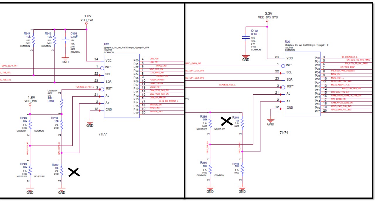
Following the traffic on UART1 debug lines on Nvidia carrier board I figured out, The error was caused by incorrect addresses on GPIO expanders. The Nvidia carrier board schematic has address 7h77 for U28 and 7h74 for U29. To get these addresses, R232 and R240 need to be NO STUFF which is not stated on the Nvidia schematic. They are not populated on development system.
After fixing this on my carrier board, it boots up fine and HDMI and USB ports function as expected.
Hello:
I refer to the carrier board designed by B04. I removed the GPIO expansion chip (U28) without using it. The other circuits are the same as the B04 carrier board, but there is no voltage output on the 5V0_HDMI_EN pin of the U29 chip after I powered it on. The USB3.0 enable has no voltage output.
Have you encountered a similar situation? Is it related to the U28 chip removal?