If you observe it is enabled as I2S4 (right side) in the PIN MUX Sheet, but the signal name we want to enable is I2S3( on the customised carrier board)
So definitely we need to reconfigure accordingly.
Thanks for the response.
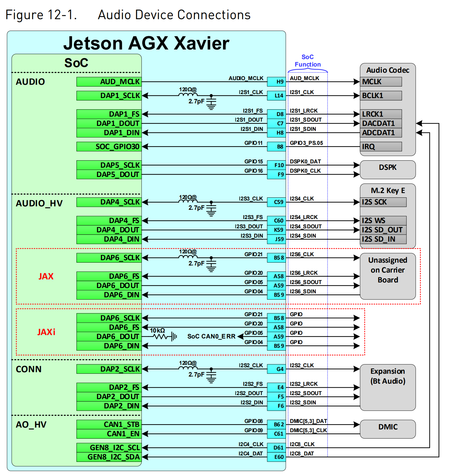
We want to use the pins: C59, K59, J59, C60.
This IS23 is connected to a Codec module on our customization board but we are not able to detect any sound.
Please let us know how to go about enabling this, as our hardware team is telling they are not able to detect it, even though the schematics for default carrier board says it is enabled and mapped to I2S4 outside.
please share your more thoughts on this. Also want to know, if there are any things which we cannot do through PINMUX spreadsheet method and we may need to enable some particular dtsi files manually?? . Any examples you have or come across
my further plan is to modify device tree “.dtsi” files in the “common” folder related to audio where there are no entry for “I2S3”. Wherever there are entries for I2S4 similarly copy and make updates for I2S3. Please let me know, if this is the correct approach as there is not much that can be done n PIN MUX sheet to make this I23S work.
Will share the dmesg command output once the customized carrier board test setup is ready.
The parent DTB file in use in our <board.conf> jetson-agx-xavier-industrial.conf which is used in flash.sh is
“tegra194-p2888-0008-p2822-0000.dtb”
not able to attach the .dtb file here. the .dtb file attachment is not supported here.
renamed the master DTB file as .TXT file for attaching here. Are u going to decode it to .DTS file and then check it? using DTC or FTDUMP command… pls clarify tegra194-p2888-0008-p2822-0000.txt (385.3 KB)
FYI. I have modified some .dtsi files in the device tree folder for I2S3 enabling by copy pasting already existing I2S4 structures. Is this the correct approach. Please clarify. Thanks.