I want to enable SPI for my AGX Orin. I reference so many command ,but still can’t enable SPI with my device. So anyone have idea?
Should I edit the pinmux spreadsheet and generate the DT file(like below picture) or just set gpio is fine.
So I should see the device in my /dev/. but I can’t see into my device.
$ modprobe spidev
I use spidev_test tool to test spidev,but dosen’t have RX, I know the reason is pins MOSI and MISO aren’t connected,So should I set gpio or pinmux or both?
First using jetson-io to configure the PINs then connect the MOSI and MISO to run the loopback test to confirm the configure.
If loopback test without problem the problem could be he in TPM chip.
Thank you for reply, how to connect the MOSI and MISO? should I set pinmux or gpio? and how to run the loopback test to confirm the configure? have any tool can help me to test?
Thank you for reply.I use the oscilloscope to test customboard MOSI and MISO pin, both of them aren’t have any singal. so I use the oscilloscope to test Orin MOSI and MISO pin, it’s work. and I compare both of my customboard and orin. I use dmesg | grep spi* command to grep spi info. I found the different is about can not get clock , like below photo:
Thank you for reply, I’m a complete beginner at this stuff
I found the error message in spi-tegra114.c as below photo:
Does tspi is a driver? if tspi is a driver how can i solve this problem? Use $ make menuconfig to loading driver?
If above command can be run successfully, the SPI master should be good, And then please add prints in tpm_tis_spi_main.c to check if the driver is run. May add prints in probe function.
Hi,
As below photo it’s my spidev0.0 test result ,and my test command is sudo ./spidev_test -v -D /dev/spidev0.0 what’s diff between you and me?
My test result doesn’t mean my SPI master is well set up on Orin?
Hi,
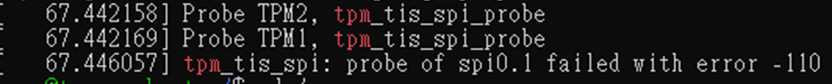
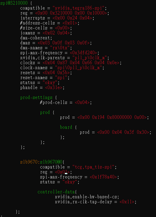
I got a new problem, I update my JP version from 5.0.2 to 5.1,and then my tpm can found in my /dev/ ,but when I modify my device tree as below photo, It’s can’t found tpm in /dev/
The number in reg should match the chip select i.e., 0 (for SPI1_CS0_N - pin24) or 1 (for SPI1_CS1_N - pin26) which you have used to connect to the TPM. if the spidev is already active in CS0, then you need to use 1 for CS1
Thank you for reply. I checked out my schematic about my TPM slb9670, I’m sure our board is use CS0 to connect TPM , that’s why I don’t understand we use CS1 can work,but CS0 can’t.