Jetson Orin AGX JP6.0: use two mcp2515 on SPI1

Hi everyone,

I would like to connect two SPI-to-CAN mcp2515 to SPI1 bus available on the 40 pin header (so pins 19, 21, 12, 24, 26) on my Orin AGX running JP 6.0.

I went through most if not all the relevant questions already answered but could not find a clear answer/guide to adding the correct device tree overlay and (how to properly apply it) to enable 2 mcp2515 over SPI 1 bus.

Here’s a list of questions I went through:

But none seems to actually give the clear guidance I am looking for (or not specific to ORIN AGX or JP 6.0…). Although I plant to use two mcp2515, even setting up a single one is causing me some headache.

The steps I took so far:

  1. wire the device on the bus
  2. enabled SPI 1 via Jetson IO. This creates an overlay which I expect to not really be enough for the task, though I am not sure whether I should modify it or add yet another overlay on top of it (which seems more what other Q&A showed)
  3. defined my own DTS (along the lines of this, but I’d be happy for a clear example fitting the usecase here!
  4. compiled it and added it to extlinux.conf Here I strongly suspect the overlay is not actually having any effect, but I am also not exactly sure how to ensure that. I do not see any new can devices appear on device list, nor anything new on device tree.

At the same time, since the mcp251x kernel module is not present on JP6.0, I compiled it from the Driver Package (BSP) Sources and loaded it.

Overall :

  • is there something I am clearly missing here?
  • could you provide a sample DTS overlay and few comments on how to apply it and ensure everything worked as expected?

Thanks for the help!

Hi federico.bennasciutti,

Are you using the devkit or custom board for AGX Orin?

Could you share the block diagram of your connections for 2 MCP2515 module on AGX Orin in case you connect something wrong?
Have you verified SPI loopback test before porting MCP2515?

Please refer to https://elinux.org/Jetson/L4T/peripheral/#MCP2515_Verification for the similar steps to port and verify MCP2515 on Jetson.
There’s only one SPI interface on 40-pins header of AGX Orin. Do you have 2 AGX Orin to verify this use case?

Hi Kevin,
I am working with Federico on the project discussed above.
Here is the block diagram you requested:


I have two AGX Orins and can work to complete the SPI loopback test as per your suggestion, thank you for the very helpful link. I’ll also try to connect a logic analyzer and see if I can’t share some screenshots if we continue to struggle.
One other question we have that I don’t think is addressed in your link is that we would like a total of 4 CAN networks on our AGX Orin. The two onboard can networks assigned to can0 and can1, and then the MCP2515 can networks assigned to can2 and can3. We will need to guarantee that the same MCP2515 is assigned to CAN2 and the same MCP2515 is assigned to CAN3 on subsequent power ups. Do you have any guidance on how the CAN2 and CAN3 assignment is guaranteed?
Thanks,
Mike

Hi KevinFFF,
I haven’t yet done the loop back test, but I do think it is becoming clear that we are struggling to load a device tree overlay to our AGX Orin 64 GB Dev Kits. In your link above you seem to be suggesting that we should modify the full device tree and reflash. To date we have been trying to apply an overlay to the existing tree.

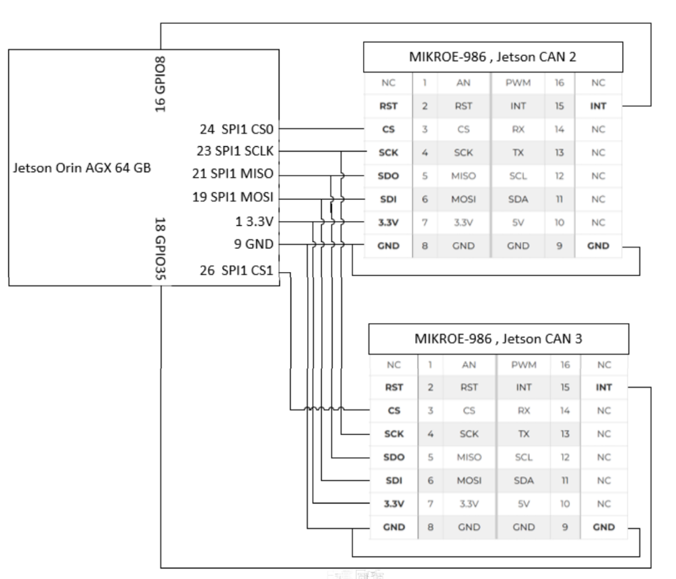
We tried to add support for both MCP2515s with the following overlay (mcp2515-dual-spi1-overlay.dts):

/dts-v1/;
/plugin/;

/ {
compatible = “nvidia,jetson-agx-orin”;

fragment@0 {
    target-path = "/spi@3210000";  // SPI1 on header
    __overlay__ {
        status = "okay";
        #address-cells = <1>;
        #size-cells = <0>;

        can2: mcp2515@0 {
            compatible = "microchip,mcp2515";
            reg = <0>; // chip select 0
            spi-max-frequency = <2000000>;
            oscillator-frequency = <10000000>;  // 10 MHz clock input
            interrupt-parent = <&tegra_main_gpio>;
            interrupts = <8 8>;
            nvidia,enable-hw-based-cs;
            controller-data {
                nvidia,enable-hw-based-cs;
                nvidia,rx-clk-tap-delay = <0x10>;
            };
        };

        can3: mcp2515@1 {
            compatible = "microchip,mcp2515";
            reg = <1>; // chip select 1
            spi-max-frequency = <2000000>;
            oscillator-frequency = <10000000>;  // 10 MHz clock input
            interrupt-parent = <&tegra_main_gpio>;
            interrupts = <499 8>;
            nvidia,enable-hw-based-cs;
            controller-data {
                nvidia,enable-hw-based-cs;
                nvidia,rx-clk-tap-delay = <0x10>;
            };
        };
    };
};

};

Then we enabled SPI1 via Jetson IO. This created a DTBO file named jetson-io-hdr40-user-custom.dtbo located in /boot. We gained access to this overlay via decompilation with this command: dtc -I dtb -O dts -o jetson-io-hdr40-user-custom.dts /boot/jetson-io-hdr40-user-custom.dtbo

This is the decompiled file:

/dts-v1/;

/ {
jetson-header-name = “Jetson 40pin Header”;
overlay-name = “User Custom [2025-05-29-141127]”;
compatible = “nvidia,p3737-0000+p3701-0000\0nvidia,p3737-0000+p3701-0004\0nvidia,p3737-0000+p3701-0005\0nvidia,p3737-0000+p3701-0008”;

p3737-0000_p3701-0000-hdr40@0 {
	target = <0xffffffff>;

	__overlay__ {
		pinctrl-names = "default";
		pinctrl-0 = <0x01>;

		exp-header-pinmux {
			phandle = <0x01>;

			hdr40-pin19 {
				nvidia,pins = "spi1_mosi_pz5";
				nvidia,function = "spi1";
				nvidia,tristate = <0x00>;
				nvidia,enable-input = <0x01>;
			};

			hdr40-pin21 {
				nvidia,pins = "spi1_miso_pz4";
				nvidia,function = "spi1";
				nvidia,tristate = <0x00>;
				nvidia,enable-input = <0x01>;
			};

			hdr40-pin23 {
				nvidia,pins = "spi1_sck_pz3";
				nvidia,function = "spi1";
				nvidia,tristate = <0x00>;
				nvidia,enable-input = <0x01>;
			};

			hdr40-pin24 {
				nvidia,pins = "spi1_cs0_pz6";
				nvidia,function = "spi1";
				nvidia,tristate = <0x00>;
				nvidia,enable-input = <0x01>;
			};

			hdr40-pin26 {
				nvidia,pins = "spi1_cs1_pz7";
				nvidia,function = "spi1";
				nvidia,tristate = <0x00>;
				nvidia,enable-input = <0x01>;
			};
		};
	};
};

fragment@1 {
	target = <0xffffffff>;

	__overlay__ {
		pinctrl-names = "default";
		pinctrl-0 = <0x02>;

		exp-header-pinmux {
			phandle = <0x02>;

			hdr40-pin29 {
				nvidia,pins = "can0_din_paa1";
				nvidia,function = "can0";
				nvidia,tristate = <0x01>;
				nvidia,enable-input = <0x01>;
			};

			hdr40-pin31 {
				nvidia,pins = "can0_dout_paa0";
				nvidia,function = "can0";
				nvidia,tristate = <0x00>;
				nvidia,enable-input = <0x00>;
			};

			hdr40-pin33 {
				nvidia,pins = "can1_dout_paa2";
				nvidia,function = "can1";
				nvidia,tristate = <0x00>;
				nvidia,enable-input = <0x00>;
			};

			hdr40-pin37 {
				nvidia,pins = "can1_din_paa3";
				nvidia,function = "can1";
				nvidia,tristate = <0x01>;
				nvidia,enable-input = <0x01>;
			};
		};
	};
};

__symbols__ {
	jetson_io_pinmux = "/p3737-0000_p3701-0000-hdr40@0/__overlay__/exp-header-pinmux";
	jetson_io_pinmux_aon = "/fragment@1/__overlay__/exp-header-pinmux";
};

__fixups__ {
	pinmux = "/p3737-0000_p3701-0000-hdr40@0:target:0";
	pinmux_aon = "/fragment@1:target:0";
};

__local_fixups__ {

	p3737-0000_p3701-0000-hdr40@0 {

		__overlay__ {
			pinctrl-0 = <0x00>;
		};
	};

	fragment@1 {

		__overlay__ {
			pinctrl-0 = <0x00>;
		};
	};
};

};

The initial extlinux.conf file looks like this :

GNU nano 6.2 ./extlinux.conf *
TIMEOUT 30
DEFAULT JetsonIO

MENU TITLE L4T boot options

LABEL primary
MENU LABEL primary kernel
LINUX /boot/Image
INITRD /boot/initrd
APPEND ${cbootargs} root=/dev/nvme0n1p1 rw rootwait rootfstype=ext4 mminit_loglevel=4 console=ttyTCU0,115200 console=ttyAMA0,115200 firmware_class.path=/etc/firmware fbcon=map:0 net.ifnames=0 nospectre_bhb video=efifb:off console=tty0 nv-auto-config

LABEL JetsonIO
MENU LABEL Custom Header Config: <HDR40 User Custom [2025-05-29-141127]>
LINUX /boot/Image
FDT /boot/dtb/kernel_tegra234-p3737-0000+p3701-0005-nv.dtb
INITRD /boot/initrd
APPEND ${cbootargs} root=/dev/nvme0n1p1 rw rootwait rootfstype=ext4 mminit_loglevel=4 console=ttyTCU0,115200 console=ttyAMA0,115200 firmware_class.path=/etc/firmware fbcon=map:0 net.ifnames=0 nospectre_bhb video=efifb:off console=tty0 nv-auto-config
OVERLAYS /boot/jetson-io-hdr40-user-custom.dtbo

we then modified the OVERLAYS line to look like this:
OVERLAYS /boot/jetson-io-hdr40-user-custom.dtbo,/boot/mcp2515-dual-spi1-overlay.dtbo and placed mcp2515-dual-spi1-overlay.dtbo in /boot.

When we make this change neither overlay functions. Our modifications in JETSONIO to add the SPI headers don’t persist, if we open JETSONIO they have reverted. If I return the OVERLAYS line to : OVERLAYS /boot/jetson-io-hdr40-user-custom.dtbo the JETSON IO changes show up again in JETSON IO.

I also experimented with combining mcp2515-dual-spi1-overlay.dts and /boot/jetson-io-hdr40-user-custom.dts into a single file and this is what results:

/dts-v1/;
/plugin/;

/ {
jetson-header-name = “Jetson 40pin Header”;
overlay-name = “User Custom with MCP2515”;
compatible = “nvidia,p3737-0000+p3701-0000\0nvidia,p3737-0000+p3701-0004\0nvidia,p3737-0000+p3701-0005\0nvidia,p3737-0000+p3701-0008”;

p3737-0000_p3701-0000-hdr40@0 {
    target = <0xffffffff>;
    __overlay__ {
        pinctrl-names = "default";
        pinctrl-0 = <0x01>;

        exp-header-pinmux {
            phandle = <0x01>;

            hdr40-pin19 {
                nvidia,pins = "spi1_mosi_pz5";
                nvidia,function = "spi1";
                nvidia,tristate = <0x00>;
                nvidia,enable-input = <0x01>;
            };

            hdr40-pin21 {
                nvidia,pins = "spi1_miso_pz4";
                nvidia,function = "spi1";
                nvidia,tristate = <0x00>;
                nvidia,enable-input = <0x01>;
            };

            hdr40-pin23 {
                nvidia,pins = "spi1_sck_pz3";
                nvidia,function = "spi1";
                nvidia,tristate = <0x00>;
                nvidia,enable-input = <0x01>;
            };

            hdr40-pin24 {
                nvidia,pins = "spi1_cs0_pz6";
                nvidia,function = "spi1";
                nvidia,tristate = <0x00>;
                nvidia,enable-input = <0x01>;
            };

            hdr40-pin26 {
                nvidia,pins = "spi1_cs1_pz7";
                nvidia,function = "spi1";
                nvidia,tristate = <0x00>;
                nvidia,enable-input = <0x01>;
            };
        };
    };
};

fragment@1 {
    target = <0xffffffff>;
    __overlay__ {
        pinctrl-names = "default";
        pinctrl-0 = <0x02>;

        exp-header-pinmux {
            phandle = <0x02>;

            hdr40-pin29 {
                nvidia,pins = "can0_din_paa1";
                nvidia,function = "can0";
                nvidia,tristate = <0x01>;
                nvidia,enable-input = <0x01>;
            };

            hdr40-pin31 {
                nvidia,pins = "can0_dout_paa0";
                nvidia,function = "can0";
                nvidia,tristate = <0x00>;
                nvidia,enable-input = <0x00>;
            };

            hdr40-pin33 {
                nvidia,pins = "can1_dout_paa2";
                nvidia,function = "can1";
                nvidia,tristate = <0x00>;
                nvidia,enable-input = <0x00>;
            };

            hdr40-pin37 {
                nvidia,pins = "can1_din_paa3";
                nvidia,function = "can1";
                nvidia,tristate = <0x01>;
                nvidia,enable-input = <0x01>;
            };
        };
    };
};

fragment@2 {
    target-path = "/spi@3210000";
    __overlay__ {
        status = "okay";
        #address-cells = <1>;
        #size-cells = <0>;

        can2: mcp2515@0 {
            compatible = "microchip,mcp2515";
            reg = <0>;
            spi-max-frequency = <2000000>;
            oscillator-frequency = <10000000>;
            interrupt-parent = <&tegra_main_gpio>;
            interrupts = <8 8>;
            controller-data {
                nvidia,enable-hw-based-cs;
                nvidia,rx-clk-tap-delay = <0x10>;
            };
        };

        can3: mcp2515@1 {
            compatible = "microchip,mcp2515";
            reg = <1>;
            spi-max-frequency = <2000000>;
            oscillator-frequency = <10000000>;
            interrupt-parent = <&tegra_main_gpio>;
            interrupts = <499 8>;
            controller-data {
                nvidia,enable-hw-based-cs;
                nvidia,rx-clk-tap-delay = <0x10>;
            };
        };
    };
};

__symbols__ {
    jetson_io_pinmux = "/p3737-0000_p3701-0000-hdr40@0/__overlay__/exp-header-pinmux";
    jetson_io_pinmux_aon = "/fragment@1/__overlay__/exp-header-pinmux";
};

__fixups__ {
    pinmux = "/p3737-0000_p3701-0000-hdr40@0:target:0";
    pinmux_aon = "/fragment@1:target:0";
};

__local_fixups__ {
    p3737-0000_p3701-0000-hdr40@0 {
        __overlay__ {
            pinctrl-0 = <0x00>;
        };
    };
    fragment@1 {
        __overlay__ {
            pinctrl-0 = <0x00>;
        };
    };
};

};

combined-mcp2515-jetsonio.dts then gets compiled via:
sudo dtc -I dts -O dtb -@ -o /boot/combined-mcp2515-jetsonio.dtbo combined-mcp2515-jetsonio.dts

extlinux.conf OVERLAYS becomes :

OVERLAYS /boot/combined-mcp2515-jetsonio.dtbo but results are similar. We lose the functionality of the JETSON IO overlay and lose the functionality associated with my MCP overlays.

Any ideas on what we’re doing wrong here? In parallel I will work on trying to see if we recompile the full device tree and flash if that resolves the issues.

Thanks very much for your help,
Mike

An easier route might be this:

It’s fully open-source, both hardware and firmware. Uses USB, so no devtree modification needed.
The schematics says that one unit could support a second CAN transceiver - no idiea if the firmware supports this.

Thank you for the suggestion! We’re hoping to prototype a more production intent solution with our development kits and as a result would like to stick to a SPI based approach. But I agree that absent that a USB to CAN adapter could work

Hi again! Thanks for the feedback!

I stand by m.gallagher0109/mg129 on the hardware setup and update to the questions.

@KevinFFF The SPI loopback test is successful on SPI1 after using Jetson IO to set SPI1 up (which in turns applies the overlay /boot/jetson-io-hdr40-user-custom.dtbo). Yet applying (or trying to do so) another overlay to actually use the MCP2515 on that same spi bus seems to fails.

Following the suggestions in MCP 2515 verification I tried rebuilding the device tree including one spi node.
Note that I used source from Jetson Linux 36.3 | NVIDIA Developer and modified the tegra234-p3737-0000+p3701-xxxx-nv-common.dtsi instead of the one mentioned in the guide as we are using an AGX Orin; I also only configured spi@3210000, as the AGX should only have that if I am not mistaken; though I am not sure whether this should bring additional changes.

I then run make dtbs and copied the resulting dtb under /boot/dtb.
The extlinux.conf file is set to use dtb mentioned above with the jetson-io-hdr40-user-custom.dtbo overlay for spi pinout.
MCP215x module is present.

Unfortunately even after rebooting, no additional can devices was present, not other indication that the procedure was successful in any way.
Side note, on the aforementioned guide, after compiling the device tree suggests to use the Jetsion-io tool to configure pinout for spi (which I had already done before that): I tried to re-run that but using the newly built dtb, Jetson-io fails to open. This makes me very suspicious about the latter device tree, but I am not sure how to gain more insight / debug it.

Assuming this is a somewhat common/standardize configuration, any chance you have on hand a diff for device tree or an overlay file that enables 2 MCP2515 on SPI1 for Jetson Orin AGX on JP 6.0? This way we can at least remove some uncertainty here

A few additional questions:

  • would you suggest compiling our own device tree (as done above), decompile-modify-recompile the device tree on the device or use overlay for the task?
  • if we need to somehow modify device tree to add mcp251x usage, would it make sense to also configure pins at the same time instead of going through Jetson-io for that? if so how?

Thanks again for all suggestions & comments

For can0 and can1, you would need 2 CAN transceivers so that they could work.
I would suggest connect CAN-H to CAN-H, CAN-L to CAN-L can check if can0 and can1 can work as expected.

Fo MCP2515, you have to confirm the driver been probed correctly.

For the devkit, I would suggest just using Jetson-IO to enable SPI and CAN.
To port MCP2515 module, you can either referring to the link I shared or just decompile the DTB on your board.

Please share the full device tree and dmesg for further check.

Hi again,

Please share the full device tree and dmesg for further check.

Here is more details:
This is the adapted tegra234-p3737-0000+p3701-xxxx-nv-common.dtsi
tegra234-p3737-0000+p3701-xxxx-nv-common.dtsi.txt (5.4 KB)

This is the decompiled device tree kernel_tegra234-p3737-0000+p3701-0005-nv.dts
base_adapted.dts.txt (154.6 KB)

This is the dmesg when booting using the above as device tree.
dmesg.txt (67.4 KB)

For can0 and can1, you would need 2 CAN transceivers so that they could work.
I would suggest connect CAN-H to CAN-H, CAN-L to CAN-L can check if can0 and can1 can work as expected.
Fo MCP2515, you have to confirm the driver been probed correctly

But how can we make sure that same physical device is assigned to can2 after every powercycle? none of the guide/answer seemed to touch this aspect explicitly which is quite relevant for production environments.

Thanks for the help!

They are assigned dynamically according to the driver been probed.
Please just check the dmesg to confirm.

[   13.685436] mttcan c310000.mttcan can0: Bitrate set
[   13.696051] mttcan c320000.mttcan can1: Bitrate set

Actually, you can also customize the aliases in device tree to assign them.

Can it work as expected if you just use 2 internal mttcan with 2 CAN transeivers?

@KevinFFF Let me clarify our setup once and for all, as I am afraid we are deviating from the core issue my colleague and myself have been trying to solve for the last few weeks.

We are would like to configure a total of 4 can interfaces on our Jetson Orin AGX devkit:

  1. can0 and can1 are currently working fine. These are using the internal can controllers and WaveShare SN65HVD230 transceiver; they have been configured thought busybox devmem to configure pins and are using mttcan drivers. These are the two interfaces you highlighted from dmesg above.

  2. can2 and can3 are currently not being detected! (thus this whole thread). We have been trying to configure these two additional can interfaces by using two mcp2515 connected to SPI1 bus (as shown in the diagram shared above) but could not successfully workout how to make the Jetson aware of the two devices on SPI1 bus. As detailed above, we followed the multitude of suggestions on the forum and adjacent resources, both related to adding overlay, as well as modifying the main device tree, without success.

  3. while following above-mentioned guidelines, we successfully compiled the mcp251x kernel module from L4T 36.3 sources as well as successfully run the SPI loopback test.

Following the guideline you shared, we recompiled the device tree as shown in the files posted here but could still not see any sign of can2 nor can3 interface. Can0 and can1 have little to do with the issue at hand here, dont’ you agree?

Along with these tests, the main and most common blocker had been the device tree overlays or modification of the base tree, supported by the fact that none of the examples provided actually matched the software & hardware configuration we have.

Overall I re-iterate my questions from above:

any chance you have on hand a diff for device tree or an overlay file that enables 2 MCP2515 on SPI1 for Jetson Orin AGX on JP 6.0?

Thanks again for the help!

Best regards,

Federico

Thanks for your clarification. It seems the current issue is specific to MCP5215 module used on AGX Orin devkit.

Okay, let’s focus on the status of two MCP2515 connected on SPI1.

                spi@3210000{
                        status = "okay";
                        spi@0 {
                               compatible = "microchip,mcp2515";
                                reg = <0x0>;
                               spi-max-frequency = <2000000>;
                               interrupt-parent = <&gpio>;
                               interrupts = <TEGRA234_MAIN_GPIO(Q, 5) IRQ_TYPE_LEVEL_LOW>;
                               clocks = <&can_clock>;
                               nvidia,enable-hw-based-cs;
                                controller-data {
                                        nvidia,enable-hw-based-cs;
                                        nvidia,rx-clk-tap-delay = <0x10>;

		rtc@c2a0000 {
			status = "okay";
		};

I’ve checked your device tree again.
There’s only the node of CS0. Where’s the configuration for SPI1_CS1?
And, do you also connect PQ.05 for interrupt as the example code? Or you just copy that configuration?

Currently, I don’t see any message indicating that MCP2515 module has been probed.

As your update here, please share the full dmesg when you can load the kernel module for MCP2515?

In addition, I also not clear about where’s CAN-H/CAN-L on MCP2515 module.
You can connect CAN-H to CAN-H and CAN-L to CAN-L for both MCP2515 module to verify loopback test.

This topic was automatically closed 14 days after the last reply. New replies are no longer allowed.