Please let me know relationship between I2C port name and i2cbus number.
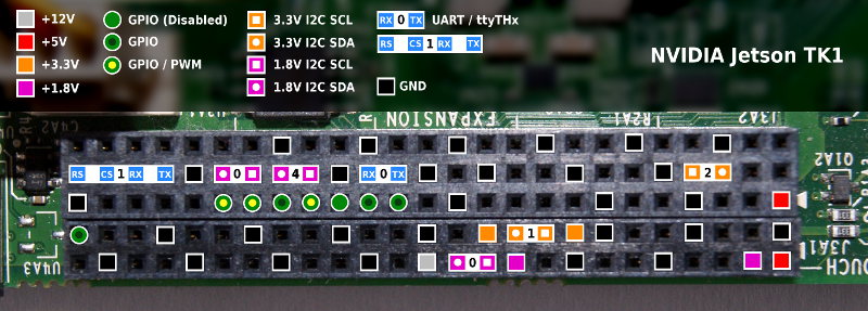
As “Jetson/I2C - eLinux.org” describes, TK1 has 6 I2C buses and 4 out of 6 are able to use on J3A1 and J3A2 connectors.
I assume that the followings from result of “i2cdetec -y #” commands and I2C address map information on the schematic.
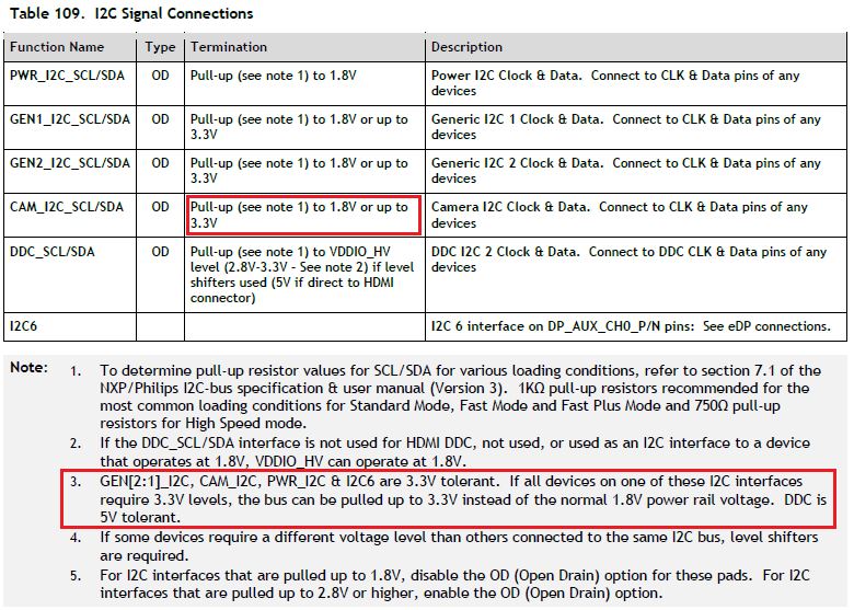
Based on the schematics, the CAM_I2C_* lines have pull-ups to 1.8V so I think the official datasheet is correct and the image above and the wiki are wrong.
AS3722 PMIC’s LDO1 voltage level determine TK1’s VDDIO_CAM voltage level which powers TK1’s CAM I/O partition power. Non-CSI camera interface.
i.e. CAM_I2C_*, GPIO_PCC[2:1], GPIOB_PBB[7:0], CAM_MCLK
From the posts above it seems like you are getting CAM_I2C to work, even if it is not at the voltage you want. I have been trying to use CAM_I2C and getting nothing. I have been able to successfully use the other three I2C lines without any issues. When I checked the voltage on each of them initially they were all in a high state, and when I send data the SCL line clocks as it should. When I check the lines for CAM_I2C though they are low be default. I can open /dev/i2c-2 without any issues, but when I send data on it the SCL line stays low the entire time. I am using the grinch 19.3.6 kernel still. I have checked the dts file and the settings for the cam_i2c are the same as for the other i2c lines. I also checked to make sure I am using pins 8 and 11 of the J3A2 header shown above. I am not sure why this is not working. Is there something special I need to do to make cam_i2c work?
What am I missing? Do I need to activate I2C somewhere else? Do I have to load a module to be able to use I2C with my GY-88 Unit? I am completely out of ideas =/
Which version of L4T are you using? The above demo was given on L4T 21.3, I do not know if I2C is enabled on earlier versions. I have been using
$ i2cdetect -y -r 1
for detecting when a device is on pins J3A1-18 and J3A1-20. I am not sure if all of the GEN2_I2C are on bus 1, but pins 18 and 20 (which are 3.3V I2C) are on bus 1.
Excellent Gerald! AFAIK, the Grinch adds support for I2C real time clocks. In my case, I did not use the Grinch to enable I2C, it just works out of the box on a stock kernel.
Hi, I’m totally new to the Jetson, Arms, device trees, and i2c.
Can someone provide a clear summary of how to get the i2c ports to use 3.3 V for the Gen and Cam lines?
According to Table 109 in youngk’s post, note 5, those ports need to have Open Drain set true. Looking at the device tree in LTK 21.4 it appears that they already are.
Here youngk says “- You need to rework CAM_I2C’s pull up resistors “R9B10 & R9B9” to be pulled up by 3.3V rail instead of default 1.8V rail in Jetson.”
What does this mean? How is this accomplished? Or is there nothing to worry about, simply connect the i2c from the Jetson to another i2c on a 3.3 V line and I’m good to go?
Hi, I’m totally new to the Jetson, Arms, device trees, and i2c.
Can someone provide a clear summary of how to get the i2c ports to use 3.3 V for the Gen and Cam lines?
According to Table 109 in youngk’s post, note 5 (see the original post, the forum won’t let me post images because I’m too new), those ports need to have Open Drain set true. Looking at the device tree in LTK 21.4 it appears that they already are.
Here youngk says “- You need to rework CAM_I2C’s pull up resistors “R9B10 & R9B9” to be pulled up by 3.3V rail instead of default 1.8V rail in Jetson.”
What does this mean? How is this accomplished? Or is there nothing to worry about, simply connect the i2c from the Jetson to another i2c on a 3.3 V line and I’m good to go?
I’m not sure about about any “safe” way to tell you about changing resistors, but many of the outputs are open-drain type and can work with any voltage within their tolerance. The output being talked about can tolerate either 1.8V or 3.3V, and the choice is via a resistor to a 1.8V power source or a 3.3V power source. One could change the resistor value and connect to a 3.3V rail instead of the existing 1.8V rail and go natively to 3.3V.
I’m attempting to connect to a slave via the gen2_i2c bus, so I expect it to show up when I do a i2cdetect -y 2. I have already confirmed that this command works with a Raspberry Pi and the slave responds with address 0x08, as I expected.
When I put a voltmeter on the pins (SCL: 18, SDA: 20, J3A1 header) I see that they are already sitting at 3.3V, so I’m assuming they are already pulled up to the 3.3 V source and that I do not need a level converter.
So the connections I have between the Jetson and my slave are SCL, SDA, 3.3 V, and GND. This configuration, without the 3.3 V line, works for me with the Raspberry Pi.
If I put an oscilloscope on the lines and do an i2cdetect -y 2 I see no change. If I try i2cdetect -y 1 then I see square pulses on SCL, but only noise on SDA.
Looking at the device tree I see that both the SDA port and the SCL port are configured to open drain.