No available cameras were found using the gstnvarguscamerasrc command

hi,

I want to adapt imx230 camera on Jetson Nano platform L4T 32.7.2 system. Need to go to ISP and run with gstreamer command. I am using the imx219 device tree to modify the imx230 device tree.

However, currently gstnvarguscamerasrc keeps showing that no camera is available. Below is the command I executed.

gst-launch-1.0 nvarguscamerasrc sensor-id=0 ispdigitalgainrange="1 1" ! "video/x-raw (memory: NVMM), width=5344, height=4012, framerate=7/1"! nvvidconv! nvoverlaysink

I had previously successfully run imx230 with gstnvarguscamerasrc on an L4T32.5.2 system. It doesn’t use jetson-io.py to select the camera.

I moved the entire device tree adapted on L4T 32.5.2 to L4T32.7.2 and abandoned jetson-io.py, and it can run normally.

But I want to apply jetson-io.py, don’t know if I am missing some important details. Can you give me some help?

hello tom153,

it’s Jetson-IO to manage the DTB overlay file (i.e. *.dtbo) selection.
had you create the *.dtbo file and including with proper override information and a compatible string?
please see-also Adding Support for Custom Hardware for details.
thanks

hi, @JerryChang

Yes, all device tree files are modified by the equipment tree of IMX219.

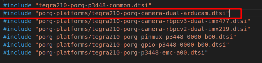
By observing different tree structures of L4T32.7.2 and L4T32.5.2, to achieve the function of Jetson-Io.py’s optional camera, “tegra210-p3448-all-p3449-0000-camera-imx219-dual.dts” The content of the file seems to be extracted from “tegra210-porg-plugin-manager.dtsi”.

Did I ignore something?

The following is my file content for Jetson-io.py to select the camera.

/dts-v1/;
/plugin/;

/ {
	overlay-name = "Camera Arducam Dual";
	jetson-header-name = "Jetson Nano CSI Connector";
	compatible = "nvidia,p3449-0000-b00+p3448-0000-b00", "nvidia,p3449-0000-b00+p3448-0002-b00";

	/* Arducam dual sensor module */
	fragment@0 {
		target = <&arducam_cam0>;
		__overlay__ {
			status = "okay";
		};
	};
	fragment@1 {
		target = <&cam_module0>;
		__overlay__ {
			status = "okay";
			badge = "porg_front_RBPCV2";
			position = "front";
			orientation = "1";
		};
	};
	fragment@2 {
		target = <&cam_module0_drivernode0>;
		__overlay__ {
			status = "okay";
			pcl_id = "v4l2_sensor";
			devname = "arducam 7-000c";
			proc-device-tree = "/proc/device-tree/cam_i2cmux/i2c@0/arducam_a@0c";
		};
	};
	fragment@3 {
		target = <&arducam_cam1>;
		__overlay__ {
			status = "okay";
		};
	};
	fragment@4 {
		target = <&cam_module1>;
		__overlay__ {
			status = "okay";
			badge = "porg_rear_RBPCV2";
			position = "rear";
			orientation = "1";
		};
	};
	fragment@5 {
		target = <&cam_module1_drivernode0>;
		__overlay__ {
			status = "okay";
			pcl_id = "v4l2_sensor";
			devname = "arducam 8-000c";
			proc-device-tree = "/proc/device-tree/cam_i2cmux/i2c@1/arducam_e@0c";
		};
	};
	fragment@6 {
		target = <&arducam_vi_in0>;
		__overlay__ {
			status = "okay";
			port-index = <0>;
			bus-width = <2>;
			remote-endpoint = <&arducam_csi_out0>;
		};
	};
	fragment@7 {
		target = <&arducam_vi_in1>;
		__overlay__ {
			status = "okay";
			port-index = <4>;
			bus-width = <2>;
			remote-endpoint = <&arducam_csi_out1>;
		};
	};
	fragment@8 {
		target = <&arducam_csi_in0>;
		__overlay__ {
			status = "okay";
			port-index = <0>;
			bus-width = <2>;
			remote-endpoint = <&arducam_dual_out0>;
		};
	};
	fragment@9 {
		target = <&arducam_csi_out0>;
		__overlay__ {
			status = "okay";
		};
	};
	fragment@10 {
		target = <&arducam_csi_in1>;
		__overlay__ {
			status = "okay";
			port-index = <4>;
			bus-width = <2>;
			remote-endpoint = <&arducam_out1>;
		};
	};
	fragment@12 {
		target = <&arducam_csi_out1>;
		__overlay__ {
			status = "okay";
		};
	};
	fragment@13 {
		target = <&imx219_cam0>;
		__overlay__ {
			status = "disabled";
		};
	};
	fragment@14 {
		target = <&imx219_cam1>;
		__overlay__ {
			status = "disabled";
		};
	};
	fragment@15 {
		target = <&imx477_cam0>;
		__overlay__ {
			status = "disabled";
		};
	};
	fragment@16 {
		target = <&imx477_cam1>;
		__overlay__ {
			status = "disabled";
		};
	};
};

hello tom153,

you should also have modify the configuration file for booting Linux (i.e. /boot/extlinux/extlinux.conf) after you created the device tree blob overlay. (i.e. *.dtbo)
please try create a new label in the extlinux.conf and adding FDT entry to specify the *.dtbo. you’ll need to choose different boot options for loading it.

hi, @JerryChang

Yes, use jetson-io.py to generate a dtb file and automatically create new tags and add FDTs in the extlinux.conf file.

jetson@ubuntu:~$ cat /boot/extlinux/extlinux.conf
TIMEOUT 30
DEFAULT JetsonIO

MENU TITLE L4T boot options

LABEL primary
      MENU LABEL primary kernel
      LINUX /boot/arducam/Image
      INITRD /boot/initrd
      APPEND ${cbootargs} quiet root=/dev/mmcblk0p1 rw rootwait rootfstype=ext4 console=ttyS0,115200n8 console=tty0 fbcon=map:0 net.ifnames=0 

# When testing a custom kernel, it is recommended that you create a backup of
# the original kernel and add a new entry to this file so that the device can
# fallback to the original kernel. To do this:
#
# 1, Make a backup of the original kernel
#      sudo cp /boot/Image /boot/Image.backup
#
# 2, Copy your custom kernel into /boot/Image
#
# 3, Uncomment below menu setting lines for the original kernel
#
# 4, Reboot

# LABEL backup
#    MENU LABEL backup kernel
#    LINUX /boot/Image.backup
#    INITRD /boot/initrd
#    APPEND ${cbootargs}

LABEL JetsonIO
	MENU LABEL Custom Header Config: <CSI Camera Arducam Dual>
	LINUX /boot/arducam/Image
	FDT /boot/arducam/dts/tegra210-p3448-0000-p3449-0000-b00-user-custom.dtb
	INITRD /boot/initrd
	APPEND ${cbootargs} quiet root=/dev/mmcblk0p1 rw rootwait rootfstype=ext4 console=ttyS0,115200n8 console=tty0 fbcon=map:0 net.ifnames=0

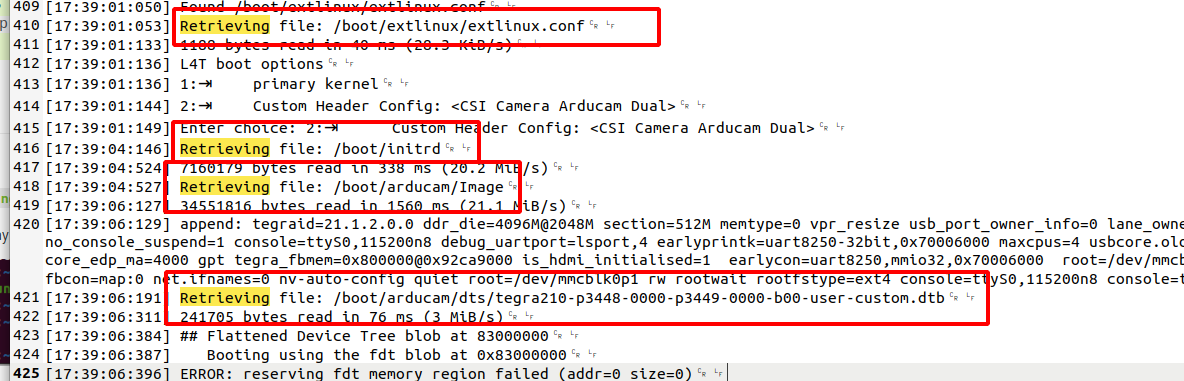
The device tree file used can be seen through dmesg.

jetson@ubuntu:~$ dmesg | grep DTS
[    0.207778] DTS File Name: /var/jenkins_home/workspace/n_nano_kernel_l4t-32.7.2-arducam/kernel/kernel-4.9/arch/arm64/boot/dts/../../../../../../hardware/nvidia/platform/t210/porg/kernel-dts/tegra210-p3448-0000-p3449-0000-b00.dts
[    0.412402] DTS File Name: /var/jenkins_home/workspace/n_nano_kernel_l4t-32.7.2-arducam/kernel/kernel-4.9/arch/arm64/boot/dts/../../../../../../hardware/nvidia/platform/t210/porg/kernel-dts/tegra210-p3448-0000-p3449-0000-b00.dts

In “tegra210-p3448-0000-p3449-0000-b00.dts” I have imported the camera related dtsi file.

hello tom153,

we need to check whether the device tree blob overlay has been loaded correctly.
could you please setup serial console and gather the bootloader logs,
it should show the message… Retrieving file:/boot/xxx.dtb while loading the *.dtbo from the FDT entry,
thanks

OK

bootloader.log (31.6 KB)

dmesg.log (56.7 KB)

hello tom153,

the file should be *.dtbo for Jetson-IO tool to apply a DTB overlay file, and the *.dtbo file should put under /boot so that the Jetson‑IO tool can recognize it.
could you please check the sysnode, please check all the camera status settings.
for example, # cat /proc/device-tree/cam_i2cmux/i2c@0/rbpcv3_imx477_a@1a/status

hi, @JerryChang

The camera state is “okay”, the camera is recognized, and the video0 node appears.

Just running gstreamer is not finding possible cameras.

As can be seen from the log:

hello tom153,

let’s narrow down the issue,
is it only using Jetson-io.py to select the dtbo to cause the failure?
could you please enable Applications Using V4L2 IOCTL Directly to check the sensor functionality.
thanks

hi, @JerryChang

The camera should be normal.

I think this problem is caused by the device tree. Does 3rd party camera need special setup to use onboard isp and gstnvarguscamerasrc.

The camera can be run via gstnvarguscamerasrc using the device tree structure of the L4T 32.5.2 system.

hello tom153,

what’s the available sensor modes reported by v4l. could you please check $ v4l2-ctl -d /dev/video0 --list-formats-ext.
may I also know what’s the pixel clock you’ve configured, please check Sensor Pixel Clock to review the settings.

OK.

image

hello tom153,

please try disable preview and shows frame-rate only with the following commands.
$ gst-launch-1.0 nvarguscamerasrc sensor-id=0 ! 'video/x-raw(memory:NVMM),width=1920, height=1080, framerate=30/1, format=NV12' ! nvvidconv ! 'video/x-raw(memory:NVMM),format=I420' ! fpsdisplaysink text-overlay=0 video-sink=fakesink sync=0 -v

please also share the kernel logs for more details, i.e. dmesg > klog.txt
thanks

hi, @JerryChang

This command still reports an error that no available camera was found.

klog.log (56.8 KB)

hello tom153,

could you please share the device tree settings,
please share the property settings in tegra-camera-platform {..} for reference,
thanks

hi, @JerryChang

OK

/ {
	tcp: tegra-camera-platform {
		compatible = "nvidia, tegra-camera-platform";

		/**
		* Physical settings to calculate max ISO BW
		*
		* num_csi_lanes = <>;
		* Total number of CSI lanes when all cameras are active
		*
		* max_lane_speed = <>;
		* Max lane speed in Kbit/s
		*
		* min_bits_per_pixel = <>;
		* Min bits per pixel
		*
		* vi_peak_byte_per_pixel = <>;
		* Max byte per pixel for the VI ISO case
		*
		* vi_bw_margin_pct = <>;
		* Vi bandwidth margin in percentage
		*
		* max_pixel_rate = <>;
		* Max pixel rate in Kpixel/s for the ISP ISO case
		*
		* isp_peak_byte_per_pixel = <>;
		* Max byte per pixel for the ISP ISO case
		*
		* isp_bw_margin_pct = <>;
		* Isp bandwidth margin in percentage
		*/
		num_csi_lanes = <4>;
		max_lane_speed = <1500000>;
		min_bits_per_pixel = <10>;
		vi_peak_byte_per_pixel = <2>;
		vi_bw_margin_pct = <25>;
		max_pixel_rate = <240000>;
		isp_peak_byte_per_pixel = <5>;
		isp_bw_margin_pct = <25>;

		/**
		 * The general guideline for naming badge_info contains 3 parts, and is as follows,
		 * The first part is the camera_board_id for the module; if the module is in a FFD
		 * platform, then use the platform name for this part.
		 * The second part contains the position of the module, ex. "rear" or "front".
		 * The third part contains the last 6 characters of a part number which is found
		 * in the module's specsheet from the vendor.
		 */
		modules {
			cam_module0: module0 {
				badge = "porg_front_RBPCV2";
				position = "front";
				orientation = "1";
				cam_module0_drivernode0: drivernode0 {
					pcl_id = "v4l2_sensor";
					devname = "arducam-jvar 7-000c";
					proc-device-tree = "/proc/device-tree/cam_i2cmux/i2c@0/arducam_a@0c";
				};
				cam_module0_drivernode1: drivernode1 {
					pcl_id = "v4l2_lens";
					proc-device-tree = "/proc/device-tree/lens_imx219@RBPCV2/";
				};
			};
			cam_module1: module1 {
				badge = "porg_rear_RBPCV2";
				position = "rear";
				orientation = "1";
				cam_module1_drivernode0: drivernode0 {
					pcl_id = "v4l2_sensor";
					devname = "arducam-jvar 8-000c";
					proc-device-tree = "/proc/device-tree/cam_i2cmux/i2c@1/arducam_e@0c";
				};
				cam_module1_drivernode1: drivernode1 {
					pcl_id = "v4l2_lens";
					proc-device-tree = "/proc/device-tree/lens_imx219@RBPCV2/";
				};
			};
		};
	};
};

hello tom153,

please modify the badge property, you may change it as… badge = "porg_front_arducam";
you may doing the same as the overlay file.

After modification, it still shows that the available camera cannot be found.

hello tom153,

may I know what’s the hardware connections, did you connect the camera board before plug-in the power-supply?