Hello,
We got 12 Jetson nano production modules and flashed them with JetPack 5.1. We designed a custom carrier with PoE for our product, however out of the 12 modules when they are on our custom carriers:
-
7 are working properly.
-
3 work as expected when they are first connected, but once they heat-up (at about 39°C) and then are rebooted or shutdown (or sometimes crashed after an hour), they will not boot again until the modules (not the custom carriers) are cooled down.
-
2 will never boot.
And these 12 modules will always work properly when connected to a carrier from the Jetson nano developer kit.
The custom carriers do not have an HDMI or a serial port. We flash the production modules on a developer kit carrier board. And in order to determine whether the modules are working properly in our custom carriers, we connect via remote ssh.
We have also verified the following:
-
The behavior of each module is consistent when connected on different units of our custom carrier.
-
Other Jetpack versions get the same results.
-
There were no issues using any of the 4 Jetson nano developer modules we had available with our custom carriers.
We have reviewed the sample schematics provided by nvidia (PCB-Rev P3449-B01) and compared them to our own but we cannot find any difference that would account for these irregularities. Could you provide any leads on how to identify the issue? Thanks a lot.
hello fernando.carrizosa1,
speaking to custom carrier board, did you follow Jetson Nano Adaptation and Bring-Up to define and have board configurations? especially the pinmux, if your board schematic differs from that for your developer kit carrier board, you must change the pinmux configuration applied by the software.
thanks
Hello JerryChang,
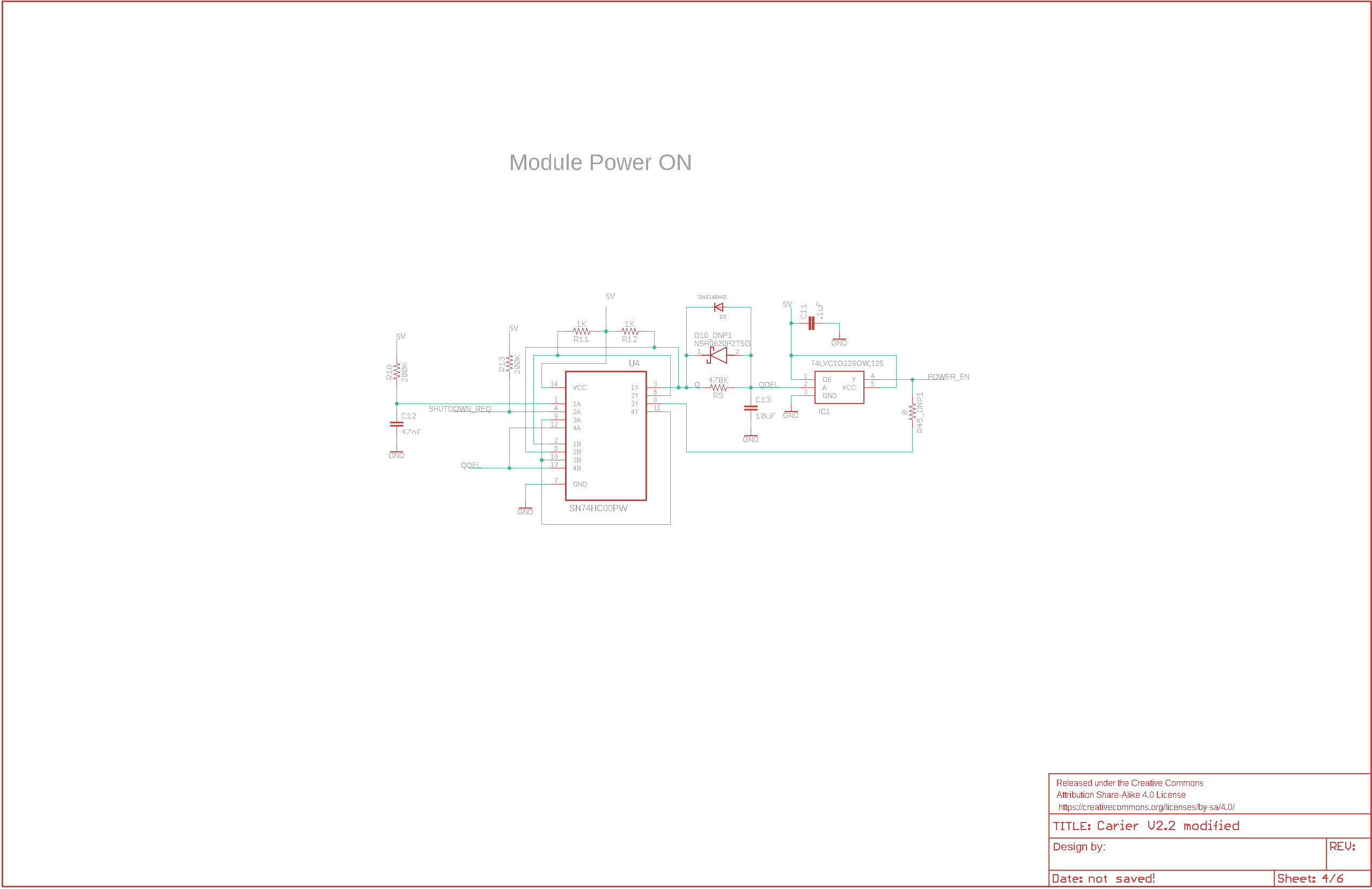
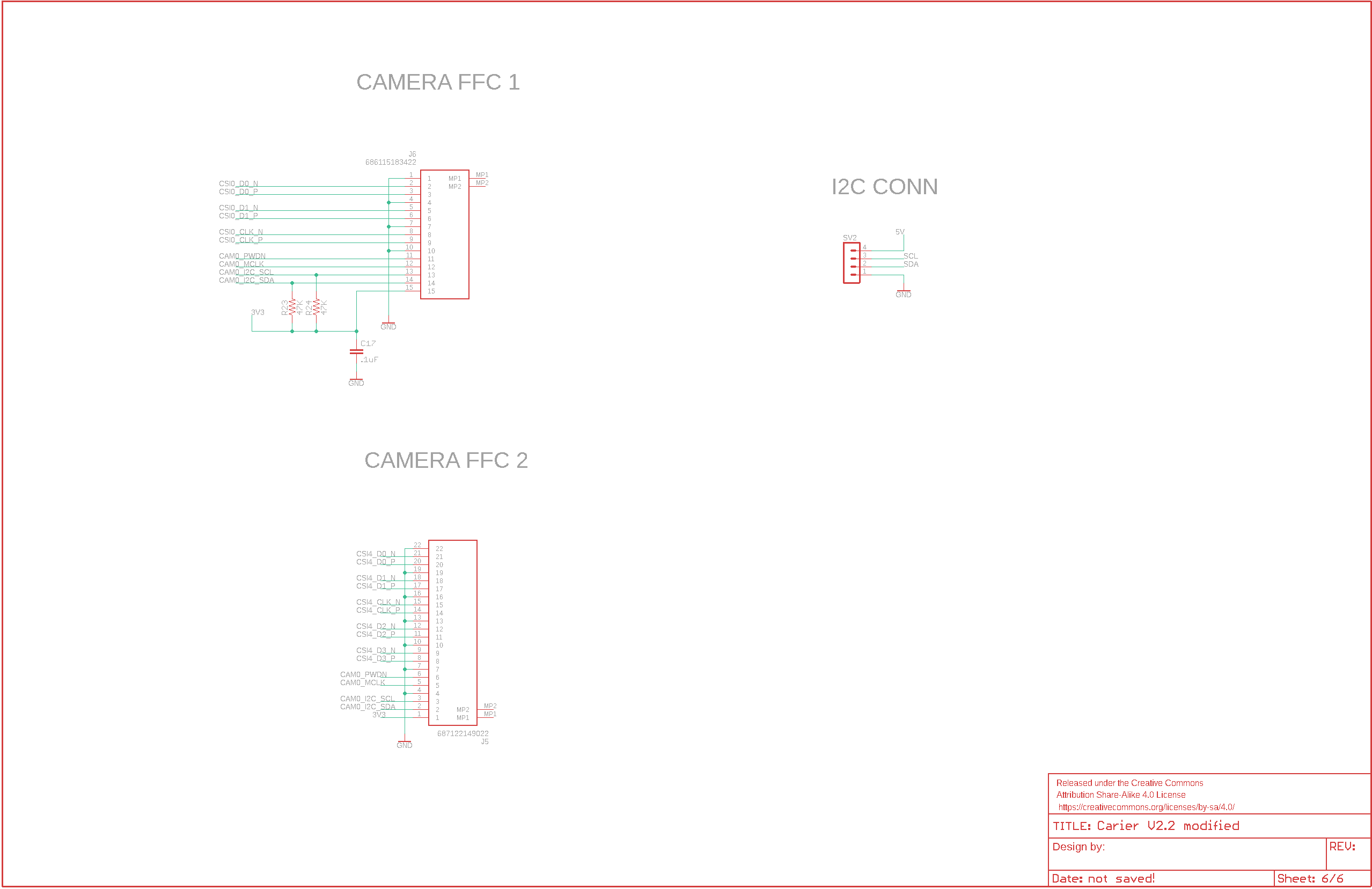
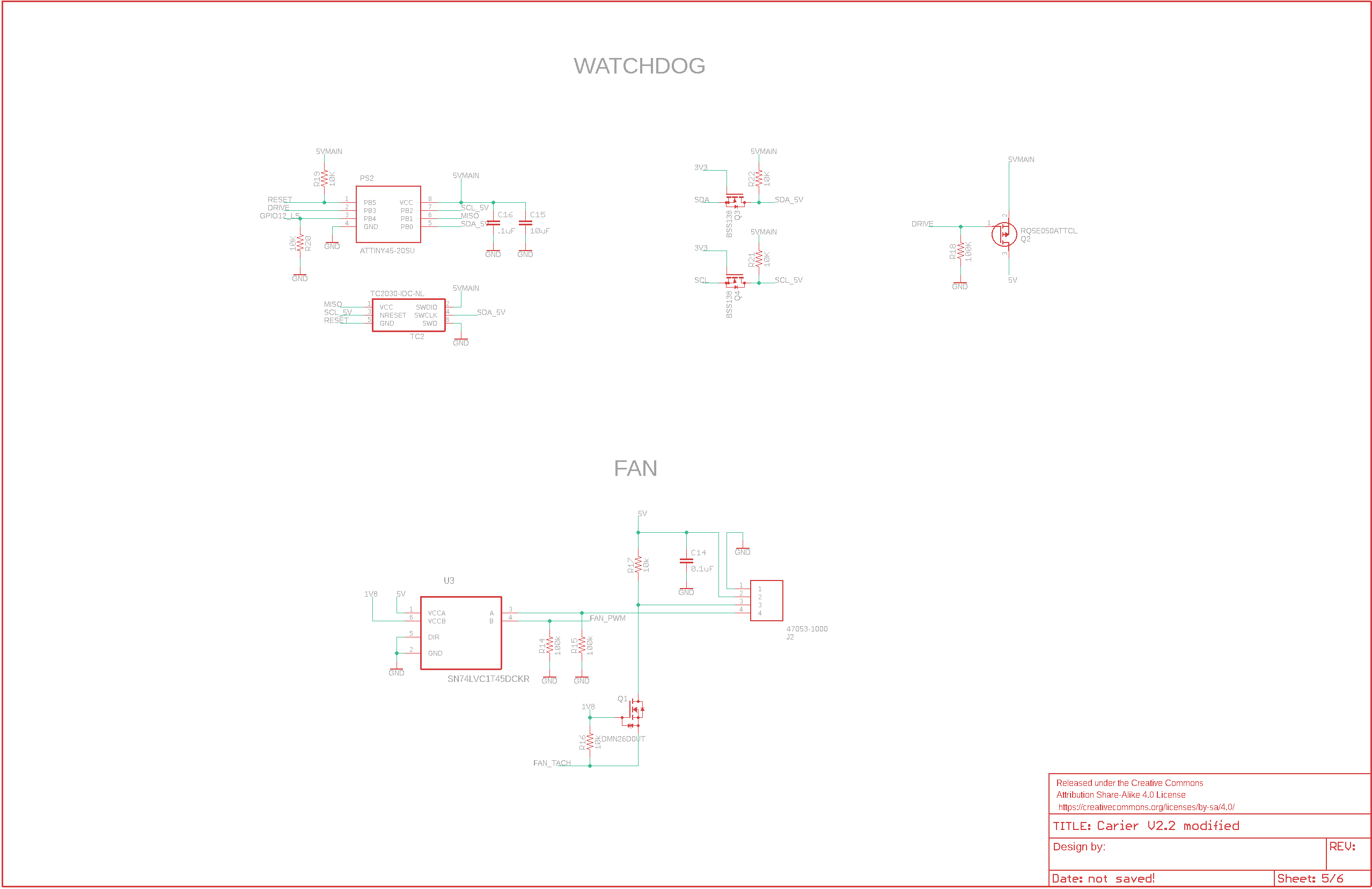
Thank you for your assistance, we followed Jetson Nano Developer Kit Pinmux Table and Jetson Nano Product Design Guide. We only removed some components and their respective routes. All the components that we did include are connected to the same pins of the module, so we did no changes to the board configuration. I attach the schematics of the custom carrier.
hello fernando.carrizosa1,
I’m not the hardware guy to read these schematics. before I arrange resources for checking, did you mean the custom carrier board is identical to developer kit carrier board?
Hello JerryChang,
The custom carrier is identical to Jetson nano reference design schematics without some connections.
hello fernando.carrizosa1,
please do follow pinmux spreadsheets to have board configurations,
and, you should also gather the failure messages for reference,
thanks
hello JerryChang,
We will try marking the unused pins in the spreadsheet and updating the Kernel. We will report the results when ready. Thanks.
you’ll need to refer to this Pinmux Changes session for the steps to customize the pinmux spreadsheet, and, use the updated device tree files to re-flash the board.
Hello JerryChang.
Thank you for your support. We have tried customizing the pinmux spreadsheet and flashing using L4T R32.5.1 (also tested L4T 32.3.1) but we always end-up on an error screen that shows “Version : […] Production node: unfused”.
There were also some parts of the instructions were we did not quite understand and interpreted as follows:
- To update the device tree image > Manually Downloading and Expanding Kernel Sources > Locate and download the L4T source files for your release.
*We downloaded “L4T Driver Package (BSP) Sources” from L4T R32.5.1 Release Page
- To update the device tree image > Copy the updated device tree image to the L4T release tree.
*We copied the files to the folder structure generated by the sdk-manager after flashing Jetpack 4.5.1 and then used the flash.sh located in the same folder
We also followed the same procedure for flashing using an unmodified pinmux spreadsheet, and in that case the error screen does not show up. Thus we suspect we may require to perform some other changes to the pinmux beyond those highlighted by the spreadsheet itself.
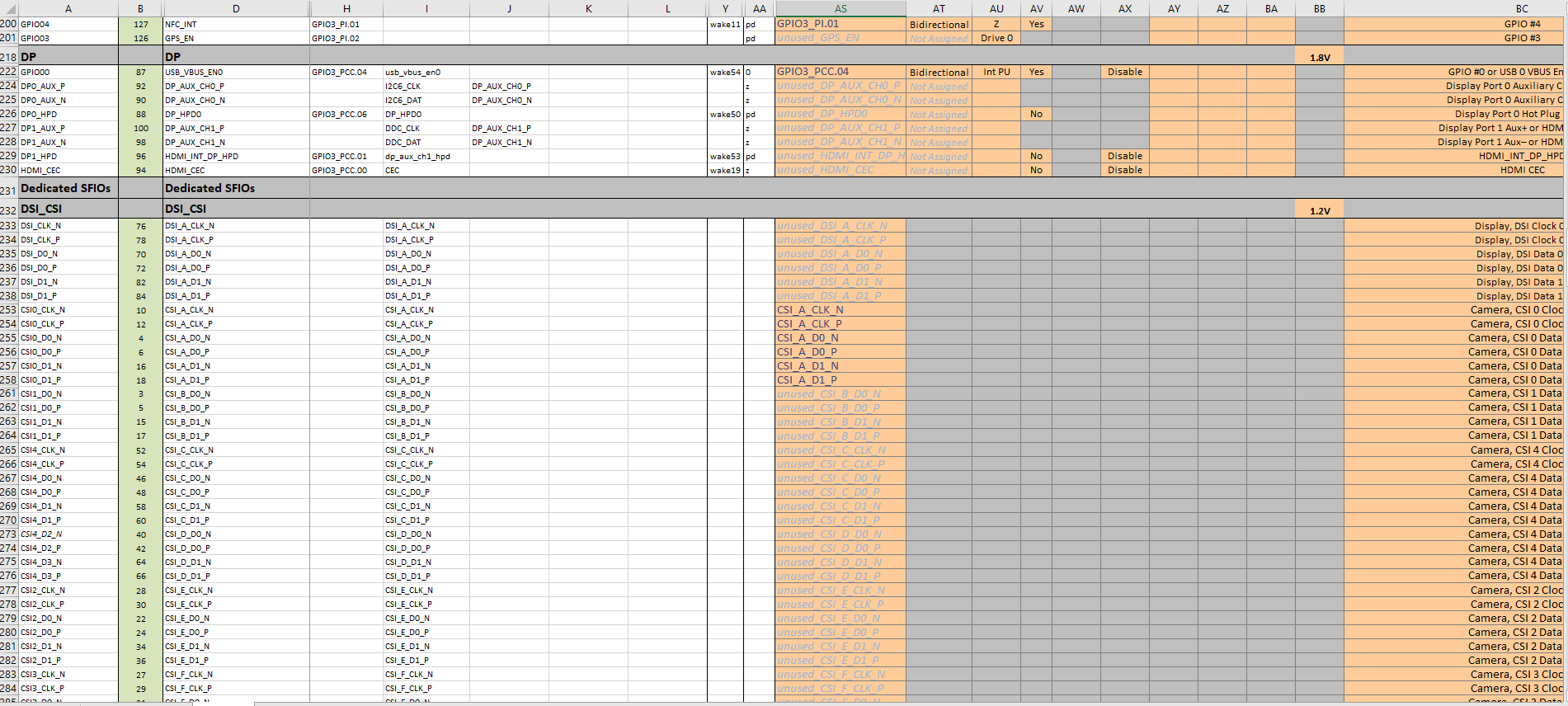
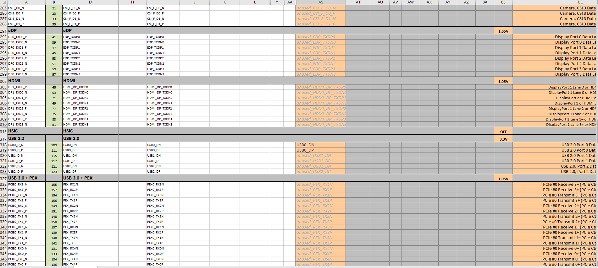
I attach some screenshots of our pinmux configuration and the error message obtained after flashing.
hello fernando.carrizosa1,
did you access Jetson Nano Pinmux via download center to have customization?
you should customize the pinmux spreadsheet to adapt to your target, overwrite the kernel sources and rebuild the dtb binary file.
we would like to check the error in details, please setup serial console and gather the bootloader logs for reference, thanks
hello JerryChang,
we re-downloaded the Pinmux spreadsheet through your link, reapplied our customization (but keeping the serial debug active to capture the logs) and repeated the process you mention. We still got the same error screen, but we gathered the logs this time.
I attach the log.
boot_log.txt (14.7 KB)
hello fernando.carrizosa1,
it looks like hardware noise detected, which might be power key long-press detected and enter the fast boot.
you should review your board schematic to resolve this from hardware side.
Just in case you want to know why we think this is a hardware issue.
This is the log from you. The first line says power button long press detected. We don’t see this happen on other users’ custom board.
[0022.320] Power button long press detected
[0022.324] Entering fastboot mode…
[0022.327] starting fastboot mode
[0022.332] fastboot cmd_init done.
[0022.335] platform does not support off-mode-charge
[0022.340] usbdcd_init Initialize USBF driver
[0022.344] usbdcd_phy_open oscfreq = 5
[0022.353] usbdcd_start Start the initialized controller
[0022.359] get_fastboot-- suspend –
_[0022.363] instructions: Error -2 finding instructions in /chosen
[0022.384] Key Code 8 not handled
hello JerryChang and WayneWWW,
thank you very much for the input but actually that log was obtained on the Jetson nano developer kit carrier using a production module with the customized DTB. We do not have a serial, usb port or HDMI on our custom carrier so we are first trying to get the pinmux configuration to work on the developer kit carrier. Using the same carrier but without customizing the DTB it does work, so it might not be a hardware issue on our developer kit carrier. Is it possible that some pinmux configuration we are using makes the module believe a button is being pressed? We will look into this fastboot mode and power button pins.
Honestly, it is a little silly to have no IO here to debug on your custom board… I would suggest you to route out a UART pin on your custom board to debug.
Can you briefly give out a table about what you’ve tried? What result is that? I see pinmux and the carrier boards are the variables here.
Also, please be aware that we won’t check each line of your pinmux spreadsheet. If you suspect pinmux is the cause, then maybe you should review what you’ve changed one by one.
And this also has no sense to “use devkit” to dump the debug log to debug the error on custom board.
We didn’t hear any of pinmux usecase that would cause the devkit enter fastboot before. Actually, we don’t know if there is such case or not. Maybe there is and you just hit it.
hello WayneWWW,
Thank you very much for your suggestions. I believe we have progressed quite a bit in solving this issue. Here is a breakdown of our tests on the devkit carrier:
-
Disable all of the pins unused by our application
Result: Fastboot mode always initiated, debug log stops just between
Kernel DTB loaded at 0x83100000
DeviceTree Init done
and
Pinmux applied successfully
-
Disable all of the pins unused by our application, except debug serial terminal
Result: Fastboot mode always initiated, debug log shows
Power button long press detected
Entering fastboot mode..
and after some lines it just repeats
Key Code 8 not handled
-
Disable all of the pins unused by our application, except debug serial terminal and BUTTON_POWER_DOWN pin (also enabling its internal pull-up)
Result: Boots successfully on the devkit carrier (no fastboot)
We managed to get the TXD serial pin out of the custom carrier and repeated the third test with 3 production modules, each one (when connected to our custom carrier) presented one of the different behaviors I listed on the initial post.
-
A module that always worked properly
Result: Boots properly.
1_success.txt (28.6 KB)
-
A module that booted properly as long as it temperature was low
Result: Boots properly while cool
2_Succes.txt (26.9 KB)
and when booting after heating-up it stopped a bit after
Hit any key to stop autoboot:
2_Fail.txt (19.3 KB)
-
A module that never booted properly
Result: Actually managed to boot properly once
3_Succes.txt (32.2 KB)
but on every other attempt it just stopped a bit after
Hit any key to stop autoboot:
3_Fail.txt (18.1 KB)
We found a post regarding the stop autoboot message where the absence of the pull-up resistor on the RXD line caused the issue and believe that might be the case for us as well.
The pinmux use case that causes the devkit to enter fastboot seems to be marking the BUTTON_POWER_DOWN as unused.
Thanks again for the help. We will report back to you once we test the RXD pin hypothesis.
hello WayneWWW,
We got the RXD pin out of the custom carrier and tested adding a pull-up resistor. All the modules we tested so far have booted properly regardless of initial temperature. We are adding the pull-up resistor and the debug port to the carrier design.
The takeaways from the whole thing being:
- Do not mark the BUTTON_POWER_DOWN as unused on the pinmux.
- Do not exclude the debug port on your carrier, or at least keep the pull-up resistor on the RXD pin.
Thanks again for the suggestions.