Found that tegra_pwm6 is in the device tree and change it to status=“okay” but cat /sys/kernel/debug/pwm does not show pwm on 0x32d00000
sudo cat /sys/kernel/debug/pwm
platform/c340000.pwm, 1 PWM device
platform/32a0000.pwm, 1 PWM device
platform/3290000.pwm, 1 PWM device
platform/3280000.pwm, 1 PWM device
/sys/class/pwm$ ls
device tree info#pwm-cells = <0x2>;
I have set up everything I know of is there a pinmux that needs to be touched to make this pwm work, I need it for lcd1_bklt_pwm right?
Terry
hello terrysu50z,
could you please examine the board configuration file for the tegra_pwm6’s settings.$OUT/Linux_for_Tegra/bootloader/t186ref/BCT/tegra186-mb1-bct-pinmux-quill-p3310-1000-c03.cfg
you may also check below similar discussion threads for reference,
examine the cfg file for what?
the LCD1_BLKT_PWM thread has been followed and the pinmux in #1 shows I have that.
What does pulse counting and fan have to do with pwm6,
**Please tell me the correct hardware to use to get LCD1_BKLT_PWM to work! is it really 0xc301a8 and if that is true please tell me which on of the pwms is attached to that pin. Need correct information to put into cfg file because you delivered R32.3.1 with the tach enabled I think instead of the generic pwm
**Or tell me where to find the tegra hardware document so I can try to figure this out myself ****
hello terrysu50z,
it’s IC Ball name is GPIO_DIS5, you may check the board configure file,
pinmux.0x0c3010a8 = 0x00000401; # gpio_dis5_pu5: gp, tristate-disable, input-disable, lpdr-disable
you should also check from kernel side for its register settings.# cat /sys/kernel/debug/tegra_pinctrl_reg | grep pu5
Got this How do I make LCD1_BLK_PWM work? what tegra_pwmx do I use?
$ sudo cat /sys/kernel/debug/tegra_pinctrl_reg | grep pu5
Could you share the full dmesg and the result of below?
xxd /proc/device-tree/pwm@32d0000/status
xxd /proc/device-tree/pwm@32d0000/status
I can give you the complete dmesg, but I think this is what is going wrong.
got this message in dmesg
ERROR: could not get clock /pwm@32d0000:pwm(0)
also this is related to Tx2-4g R32.3.1 pwm@32d0000 configuration fail
Don’t know how to link to another thread
Terry
should be this one, Tx2-4g R32.3.1 pwm@32d0000 configuration fail , right?
I just want LCD1_BLK_PWM to work.
Ok, we all know you want LCD1_PWM_BKLT.
Still need your full dmesg and full dts here. Please attach.
deviceTree (254.6 KB) dmesg.txt (78.1 KB)
The files you asked for, using pwm_led to point at &tegra_pwm6 and 0x0c03010a8 is 0x401, but pwm6 init/dmesg shows pwm6 clock is missing.
Terry
Bibek
February 1, 2021, 11:44am
18
please dont use PWM6. Is it coming out of the CVM module for you to use?
Hi,
Sorry that I didn’t notice this. If you want to use LCD1_PWM_BKLT, then you should not use pwm6.
Below snippet is from the pwm. Please check this section and pick up the correct pwm you want to use.
Still I ask again, please answer this! This simple question is taking Nvidia months to answer!
what pwm is connected to pinmux 0x0c03010a8
What is the correct pinmux for LCD1_BLKT_PWM and what is the correct pwm? for LCD1_BLKT_PWM
Terry
Hi,
0x0c03010a8 is the LCD1_BLKT_PWM. This is correct.
Still I ask again, please answer this! This simple question is taking Nvidia months to answer!
Now which pwm is for LCD1_BLK_PWM, you have never said!
Hi,
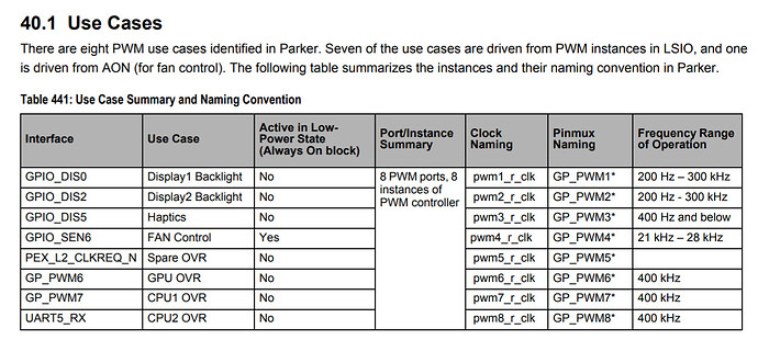
Use these two tables and you should be able to use pwm3 for that pwm.
Please explain how you get pwm3 from these two tables, where do I find the LCD1_BLKT_PWM to tegra_pwm mapping?
I will try pwm3, thanks,
Hi,
Open your pinmux spread sheet. This line will tell you this pinx is GPIO_DSI0.
Or just checked @JerryChang ’s comment above. He already told you the pin GPIO_DIS5.
Then, check the table from TRM, which I posted above. You should be able to get pwm3.
you need to use the spread sheet and the two tables to get the right information.
tried tegra_pwm3, the hardware guy said it did not work.
How do I make LCD1_BLKT_PWM work?
Thanks,


