[![enter image description here][2]][2]
I run a video recorder in a vehicle built on Jetson Nano. The vehicle has a 24V power supply. I power the video recorder with an automotive-grade 24V to 5V converter.
The Jetson nano is connected with a Raspberrypi Camera with a Flat ribbon cable. When I record video, I get a wave-like noise on the video feed at random times. And at times, it appears in a 1 second interval(only from what I see, no measurements/tests done) . This is the connection diagram and voltage differences between nodes.

The software guys working on the camera driver say this could be electrical interference. We have a similar setup in our lab environment and we are not able to reproduce the noise. We doubted the power supply, vibration, 4G LTE interference, GPS interference. The cable used to connect the camera with the board sometimes touches the HDMI/display ports of the Jetson Nano board.
Sample video of different types of noises:
busnet0_samples_00004_sample2.mp4 - Google Drive
busnet0_samples_00004_sample1.mp4 - Google Drive
ezgif.com-crop.mkv - Google Drive
Sometimes the lines are coloured and some times the are white
Is this caused by ground loops?
What could be different from a vehicle and the lab environment, how do I ensure the grounding is good in the vehicle. And how do I test and ensure if this is due to electrical interference? Or any other interference?
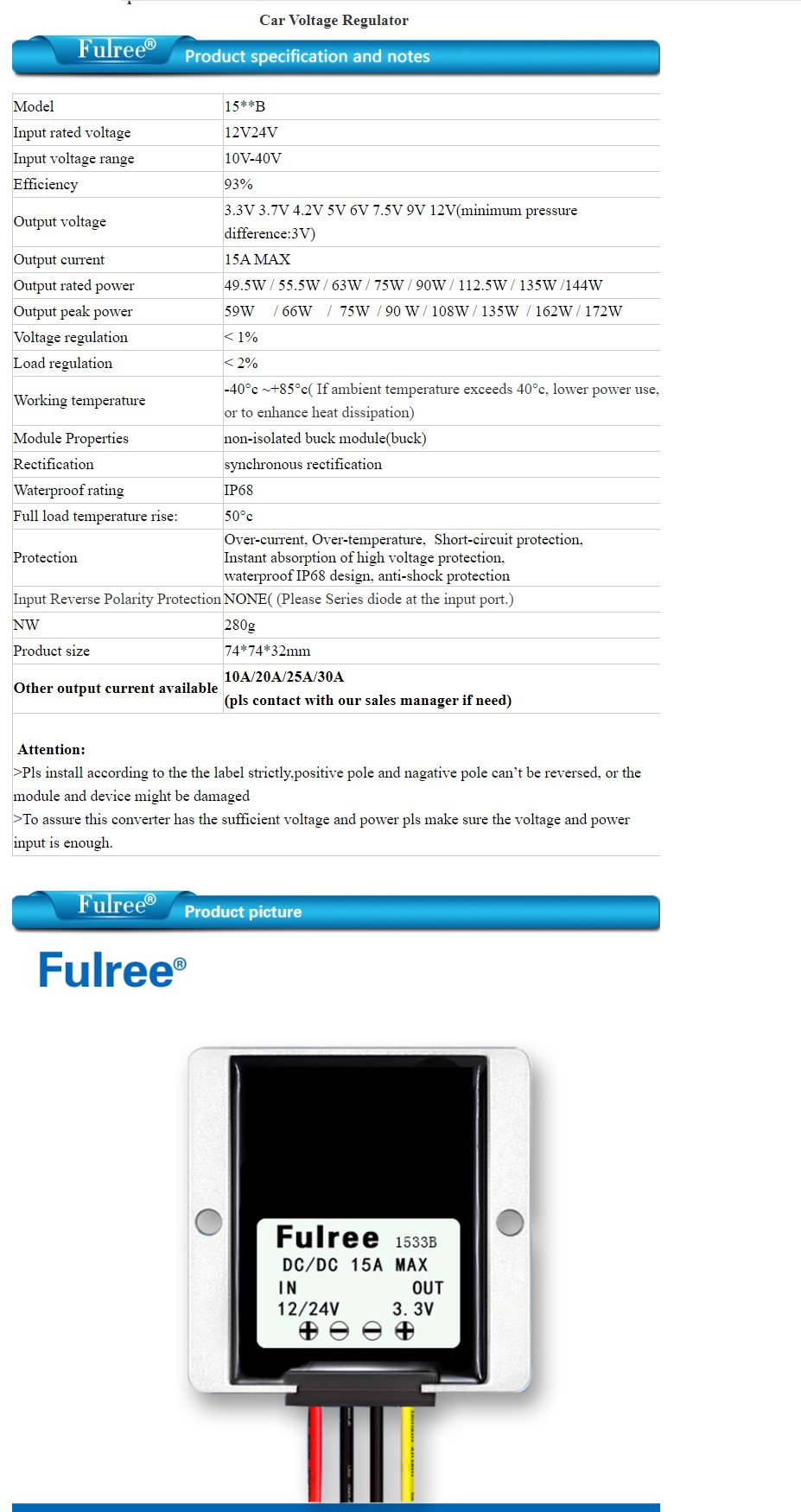
This is the convertor used, the sellers say this is non-isolated buck converter and there are isolated ones which are used in radio related devices for less noise, does this have anything to do?