Hello,
I am planning to have a 6S battery so about max of 25.2V as the input voltage to my carrier board. I am wondering where and it what ways I will have to make changes to the schematic of the xavier nx devkit carrier board.
I will have to change the zener diode voltage, have some higher voltage rated capacitors and maybe have more capacitors since the noise caused by the motors of a drone which this carrier board will be on is high. Also since voltage fluctuation should be expected to be high, maybe I should also have quite a margin between the battery max voltage and the voltage rating of the capacitor. Is this correct?
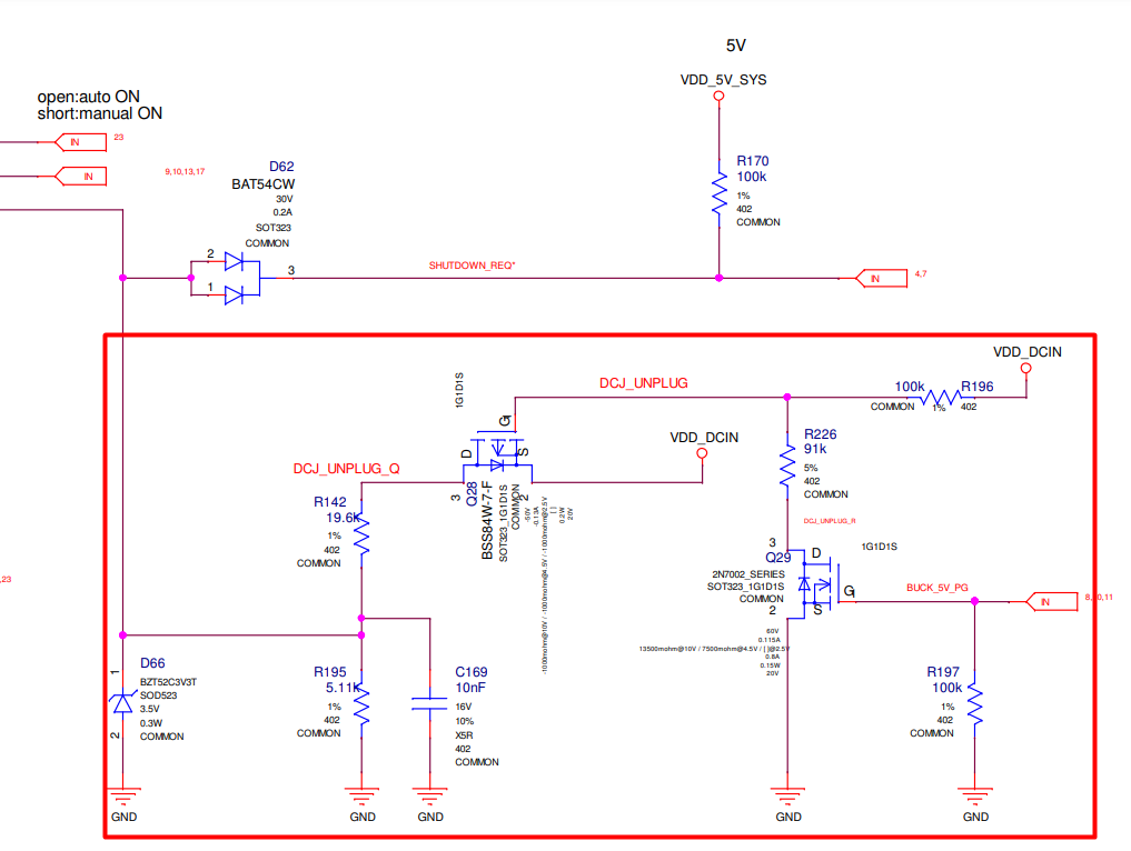
I am also wondering if the DC Jack unplug circuit on the button Power MCU schematic page has to be changed because of the higher voltage of the battery since I don’t quite understand the circuit and haven’t found an explanation on this circuit.
Here is the circuit I am talking about:
Thanks in advance,
Daniel